P0510
DTC P0510 Closed Throttle Position Switch (Idle Switch) MalfunctionWiring Diagram:
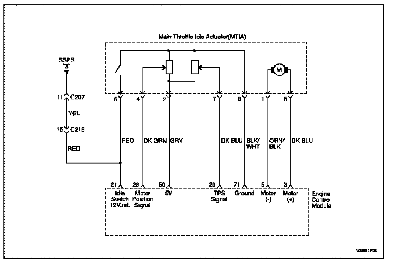
Circuit Description
The aim of the MTIA (Main Throttle Idle Actuator) is to control the idle speed with the throttle body itself. The throttle is motorized for low opening angle (0, 18 °). The characteristics of the air flow are not the same for low and high opening angles. As a matter of fact, the gradient of the mass air flow function of TP sensor is lower for small angles that permits to be more precise during the idle speed control. Out of idle speed the throttle is actuated mechanically by a classical bowdencable.
This switch indicates throttle plate in idle position when contact closed. This switch is fixed at the DC-motor drive and the throttle plate closes the contact in dependence to the actual motor drive position.
Conditions for Setting the DTC
- The engine stopped and ignition switch turned ON.
- MTIA output signal is higher than throttle position -0.5 ° and throttle position is open at least 0.2 seconds.
Or
- Engine is running.
- The throttle position Sensor is greater than 27 °.
Action Taken When the DTC Sets
- The Malfunction Indicator Lamp (MIL) will illuminate.
- The ECM will record operating conditions at the time the diagnostic fails. This information will be stored in the Freeze Frame and Failure Records buffers.
- A history DTC is stored.
Conditions for Clearing the MIL/DTC
- The MIL will turn off at the end of 3 consecutive ignition cycles in which the diagnostic runs without a fault.
- A history DTC will clear after 40 consecutive warm up cycles without a fault.
- Using the scan tool can clear DTC(s).
Diagnostic Aids
An Intermittent problem may be caused by a poor connection, rubbed through wire insulation, or wire that is broken inside the insulation.
VSS signal circuit should be thoroughly checked for the following conditions
- Backed-out terminals
- Improper mating
- Broken locks
- Improperly formed
- Damaged terminals
- Poor terminal to wire connection
- Physical damage to the wiring harness
Ensure the VSS is correctly torqued to the transaxle housing.
Refer to Intermittents. Intermittents
Step 1 - 7:
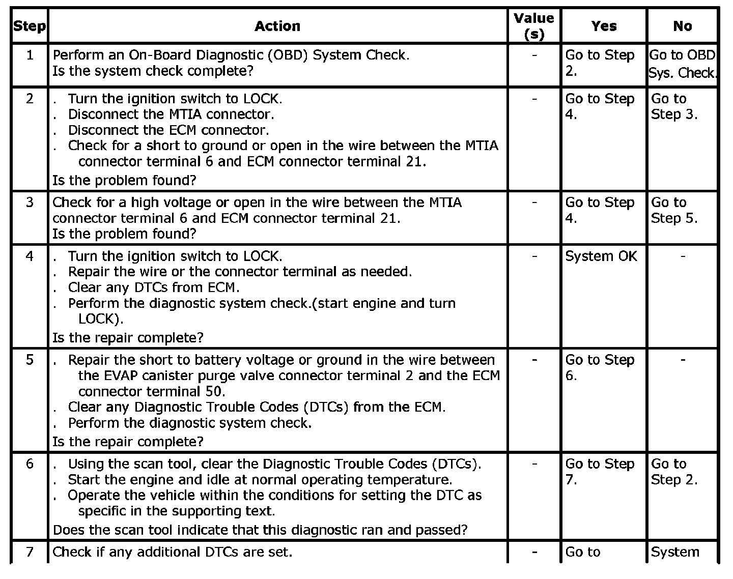
Step 7 (Contd.):

DTC P0510 - Closed Throttle Position Switch (Idle Switch) Malfunction