P0128
DTC P0128 Thermostat Stuck OpenWiring Diagram:
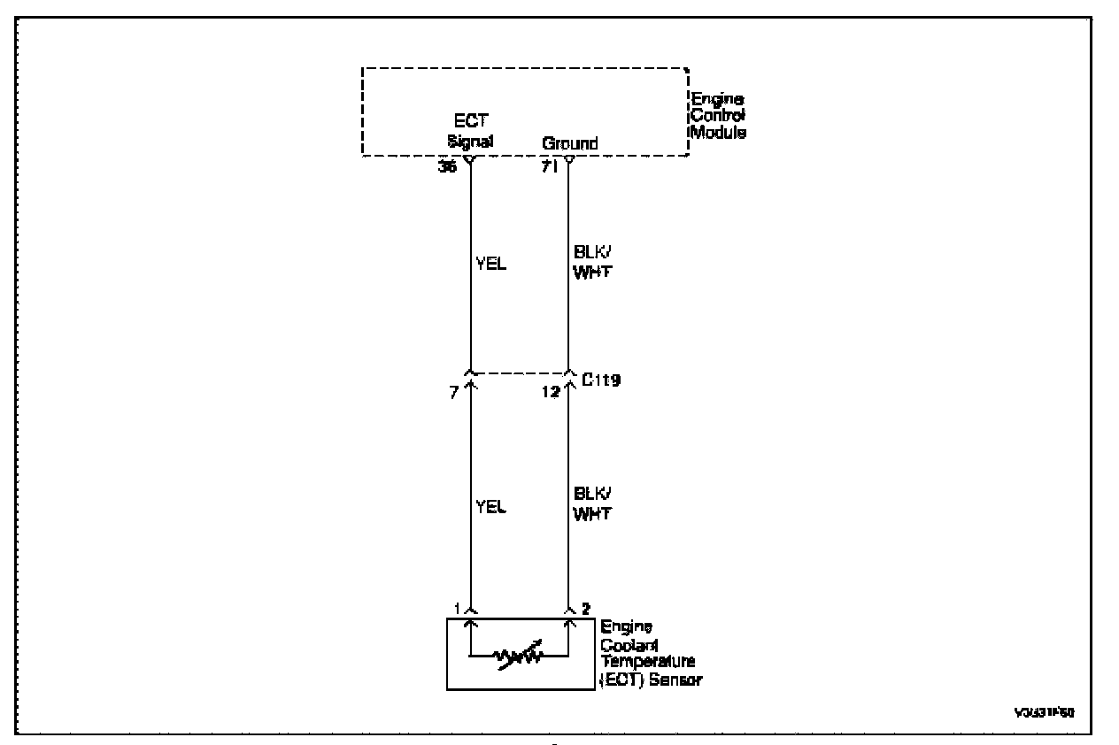
Circuit Description
The Engine Coolant Temperature (ECT) Sensor uses a thermistor to control the signal voltage to the Engine Control Module (ECM). The ECM supplies a voltage on the signal circuit to the sensor. The output varies as the ECT increases. At normal engine operating temperature, the voltage will be between 1.5 and 5 volts at the ECT signal terminal.
When the vehicle is first started, the ECM monitors the ECT and determines if it reaches a specified temperature level within a predetermined time. The time is based on Intake Air Temperature (IAT) and the start-up ECT. The Malfunction Indicator Lamp (MIL) is illuminated and DTC P0128 is set when a stuck open thermostat prevents the engine coolant from reaching the predetermined operating conditions.
Conditions for Setting the DTC
- No excessive load on the engine running.
- Intake air temperature (IAT) decrease compared to starting IAT is greater than -10 °C (-18 °F), or 10 °C (18 °F) during the Federal Test Procedure -75 (FTP-75).
- Starting coolant temperature is between -10 °C (14 °F) and 75 °C (167 °F).
- Starting intake air temperature is higher than -10 °C (14 °F).
- ECT signal value is less than 75 °C (167 °F) when the compensated coolant temperature is over 85.5 °C (185.9 °C)
Action Taken When the DTC Sets
- The Malfunction Indicator Lamp (MIL) will illuminate.
- The ECM will record operating conditions at the time the diagnostic fails. This information will be stored in the Freeze Frame and Failure Records buffers.
- A history DTC is stored.
Conditions for Clearing the MIL/DTC
- The MIL will turn off at the end of three (3) consecutive validation cycles in which the diagnostic runs without a fault.
- A history DTC will clear after 40 warm up cycles without a fault.
- DTC(s) can be cleared by using the scan tool.
Diagnostic Aids
When DTC P0128 is set, a skewed ECT sensor or a stuck-open thermostat is indicated.
An intermittent may be caused by a poor connection, rubbed-through wire insulation or a wire broken inside the insulation.
Check for a poor connection or damaged ECM harness. Inspect the ECT sensor signal circuit and ground circuit terminals for the following conditions:
- Improper mating
- Broken locks
- Improperly formed
- Damaged terminals
- Poor terminal-to-wire connection
- Damaged harness
Perform an intermittent test. If connections and harness check OK, monitor a digital voltmeter connected between ECT sensor signal circuit and ground circuit terminals while moving related connectors and wiring harness. If a fault is induced, the resistance reading will change. This may help to isolate the location of the malfunction.
Use the Temperature vs. Resistance table to evaluate the possibility of a skewed sensor.
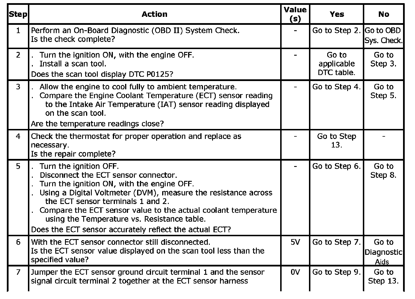
Step 1 - 7:
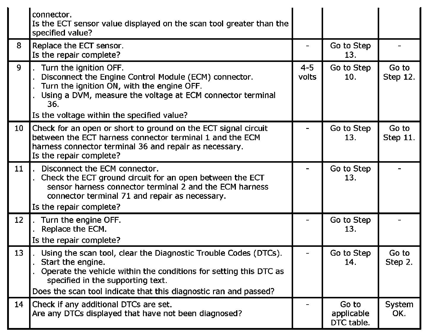
Step 8 - 14:
DTC P0128 - Thermostat Stuck Open