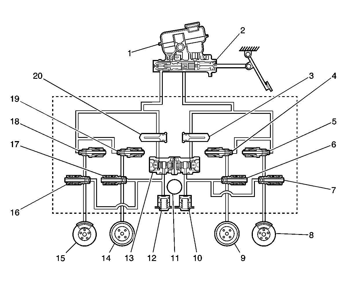
Hydraulic Diagram: Notes
 Courtesy of GENERAL MOTORS CORP.
| Callout |
Component Name |
| 1 |
Reservoir |
| 2 |
Master Cylinder |
| 3 |
Damper |
| 4 |
Inlet Valve |
| 5 |
Inlet Valve |
| 6 |
Outlet Valve |
| 7 |
Outlet Valve |
| 8 |
Left Front |
| 9 |
Right Front |
| 10 |
Accumulator |
| 11 |
Motor |
| 12 |
Accumulator |
| 13 |
Pump |
| 14 |
Left Rear |
| 15 |
Right Front |
| 16 |
Outlet Valve |
| 17 |
Outlet Valve |
| 18 |
Inlet Valve |
| 19 |
Inlet Valve |
| 20 |
Damper |
 Courtesy of GENERAL MOTORS CORP.
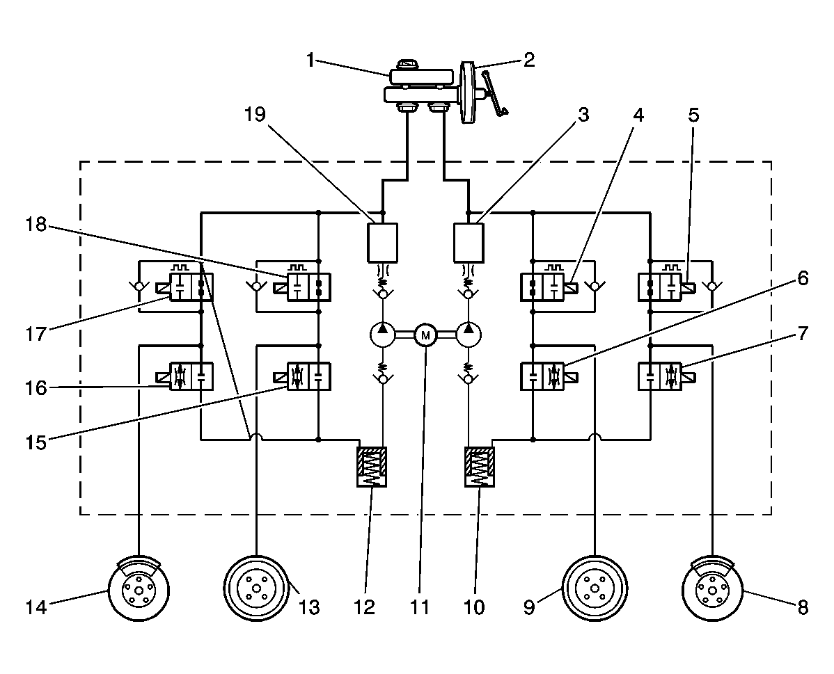
| Callout |
Component Name |
| 1 |
Reservoir |
| 2 |
Master Cylinder |
| 3 |
High Pressure Accumulator |
| 4 |
Inlet Valve |
| 5 |
Inlet Valve |
| 6 |
Outlet Valve |
| 7 |
Outlet Valve |
| 8 |
Left Front |
| 9 |
Right Rear |
| 10 |
Low Pressure Accumulator |
| 11 |
Motor |
| 12 |
Low Pressure Accumulator |
| 13 |
Left Rear |
| 14 |
Right Front |
| 15 |
Outlet Valve |
| 16 |
Outlet Valve |
| 17 |
Inlet Valve |
| 18 |
Inlet Valve |
| 19 |
High Pressure Accumulator |
The purpose of the anti lock brake system (ABS) modulator is to minimize wheel slip during heavy braking. The brake modulator performs this function by monitoring the speed of each wheel and controlling the brake fluid pressure to each wheel independently during a braking event. This allows the driver to retain directional stability and better steering capability.