Inspection of ECM (PCM) and Its Circuits
Inspection of ECM (PCM) and Its CircuitsECM (PCM) and its circuits can be checked at ECM (PCM) wiring couplers by measuring voltage, pulse signal and resistance.
CAUTION: ECM (PCM) cannot be checked by itself. It is strictly prohibited to connect voltmeter or ohmmeter to ECM (PCM) with couplers disconnected from it.
Voltage and Signal Check
Viewed from Harness Side:
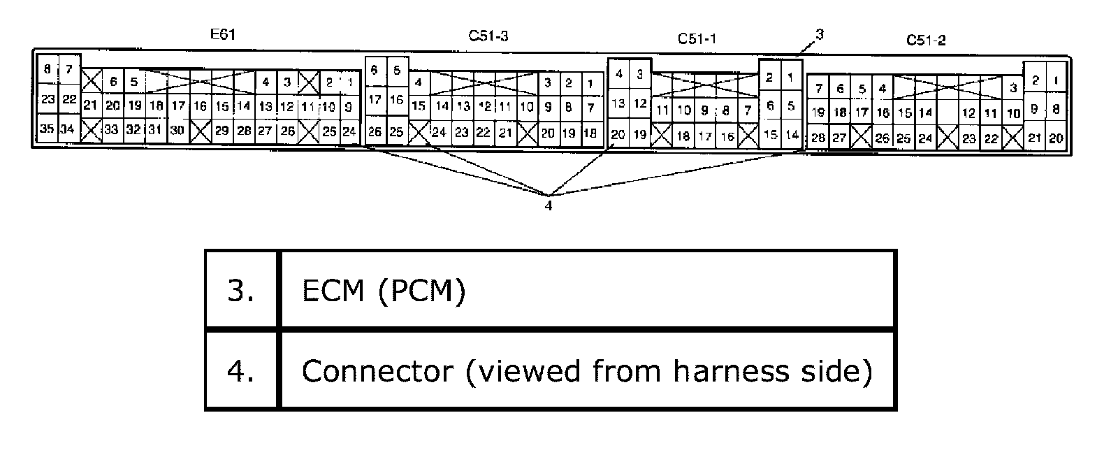
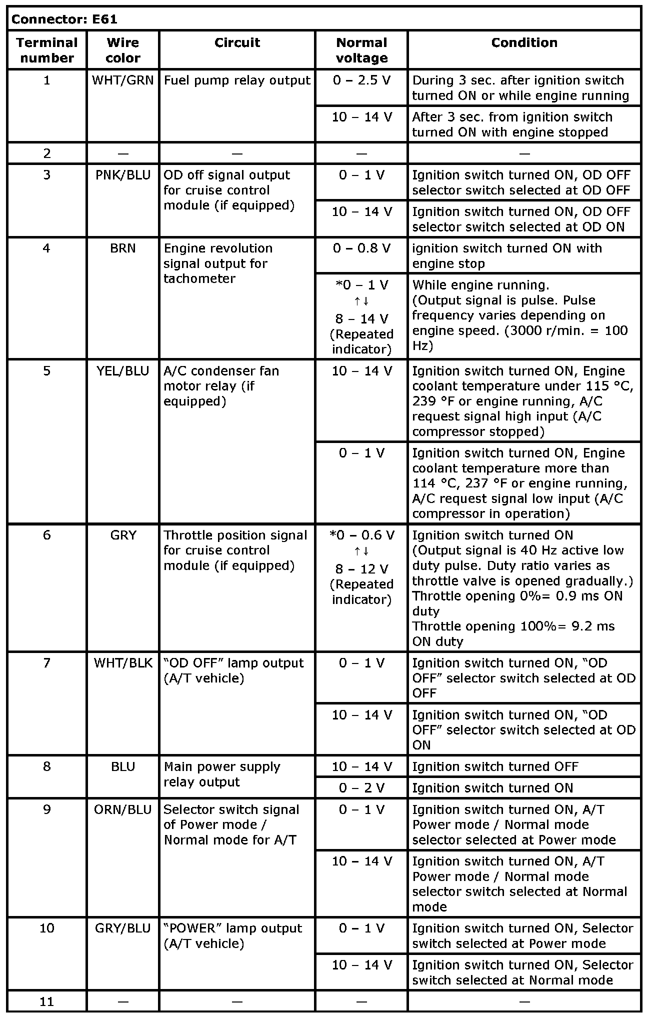
Ter. E61-1 - E61-11:
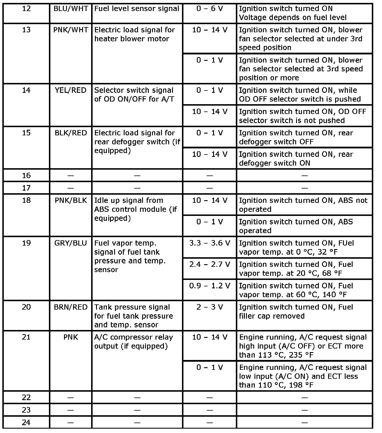
Ter. E61-12 - E61-24:
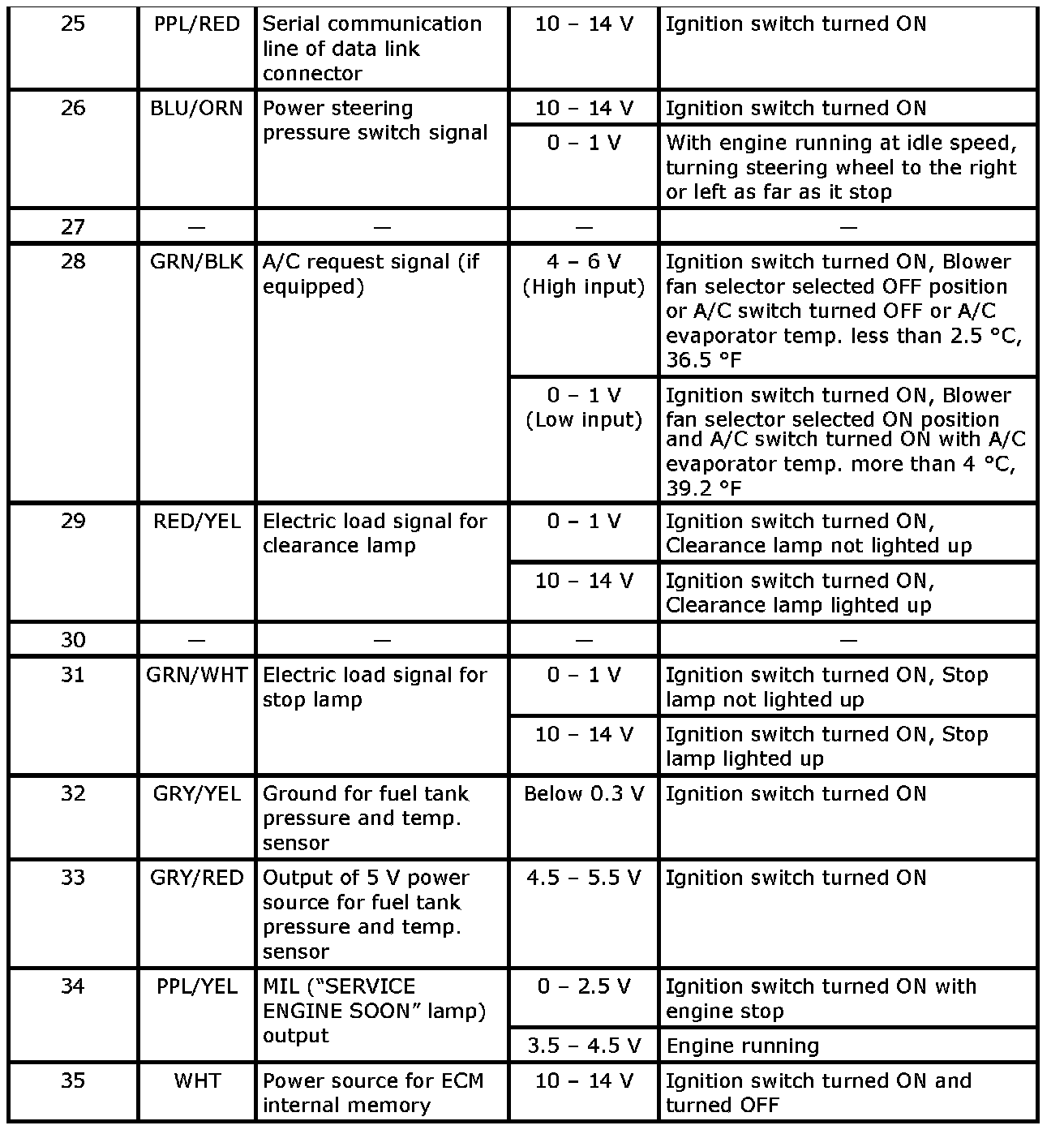
Ter. E61-25 - E61-35:
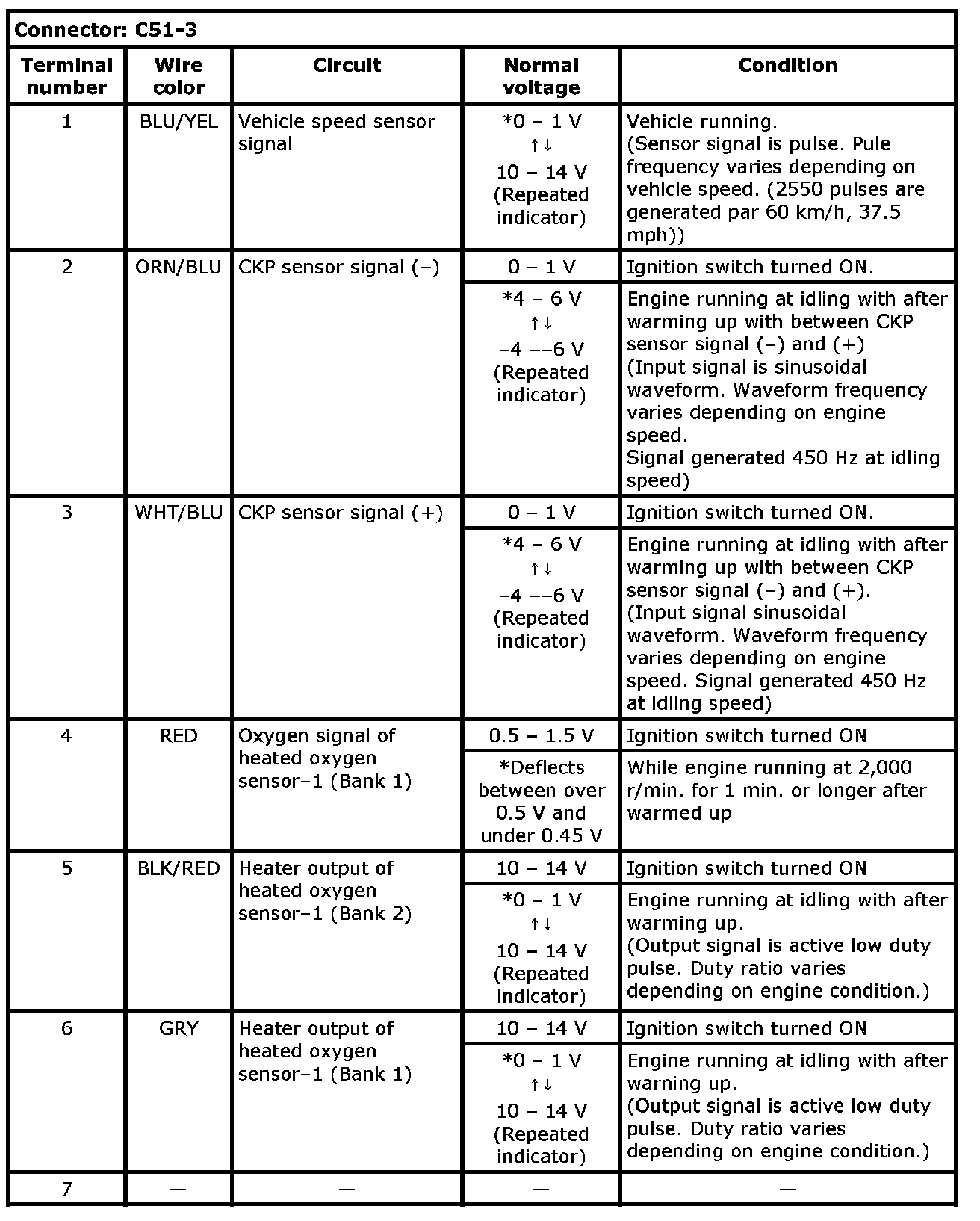
Ter. C51-3-1 - C51-3-7:
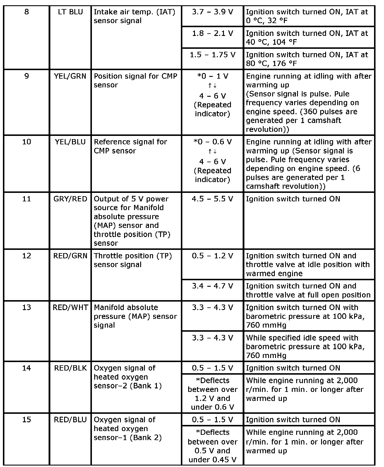
Ter. C51-3-8 - C51-3-15:
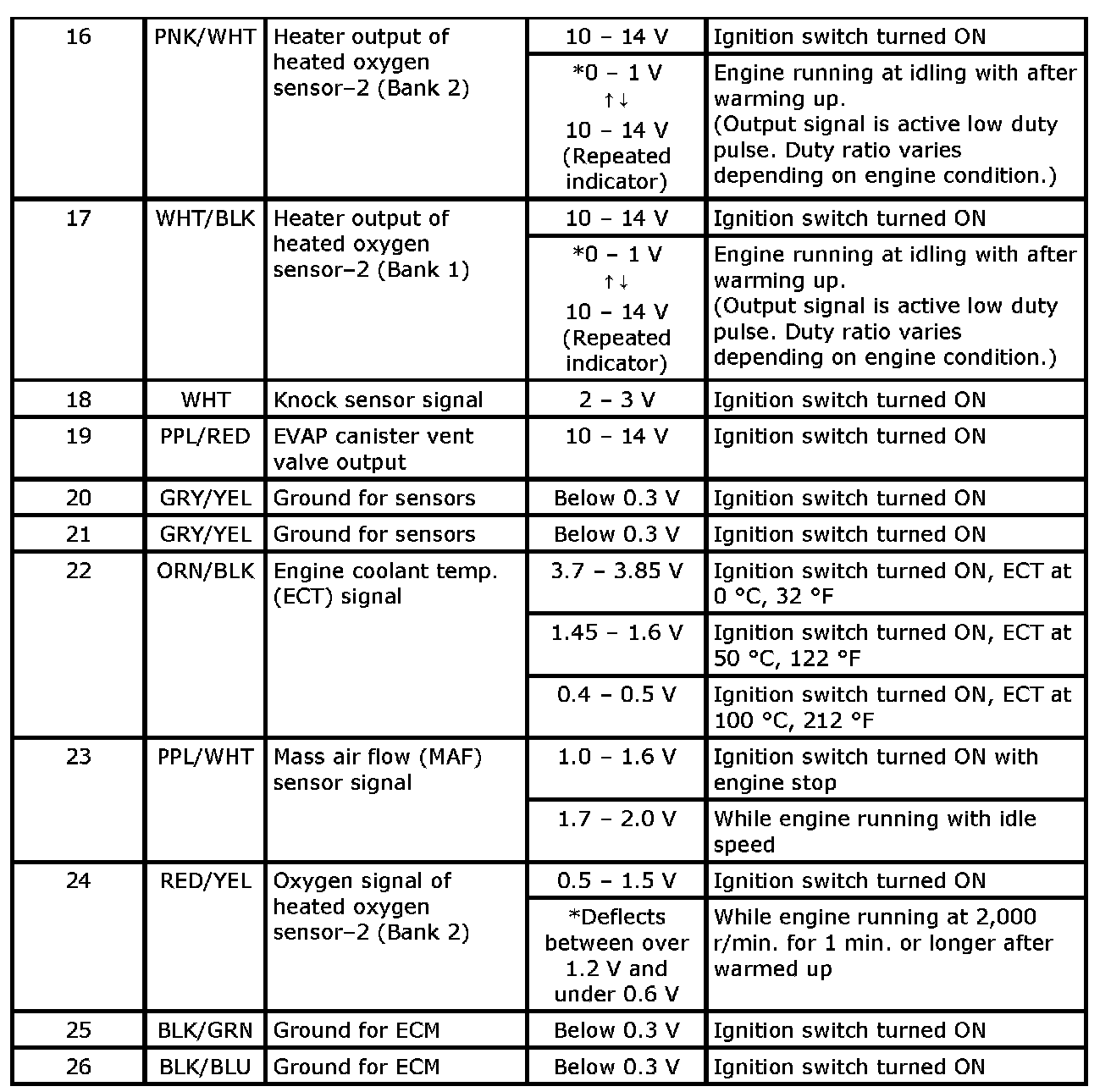
Ter. C51-3-16 - C51-3-26:
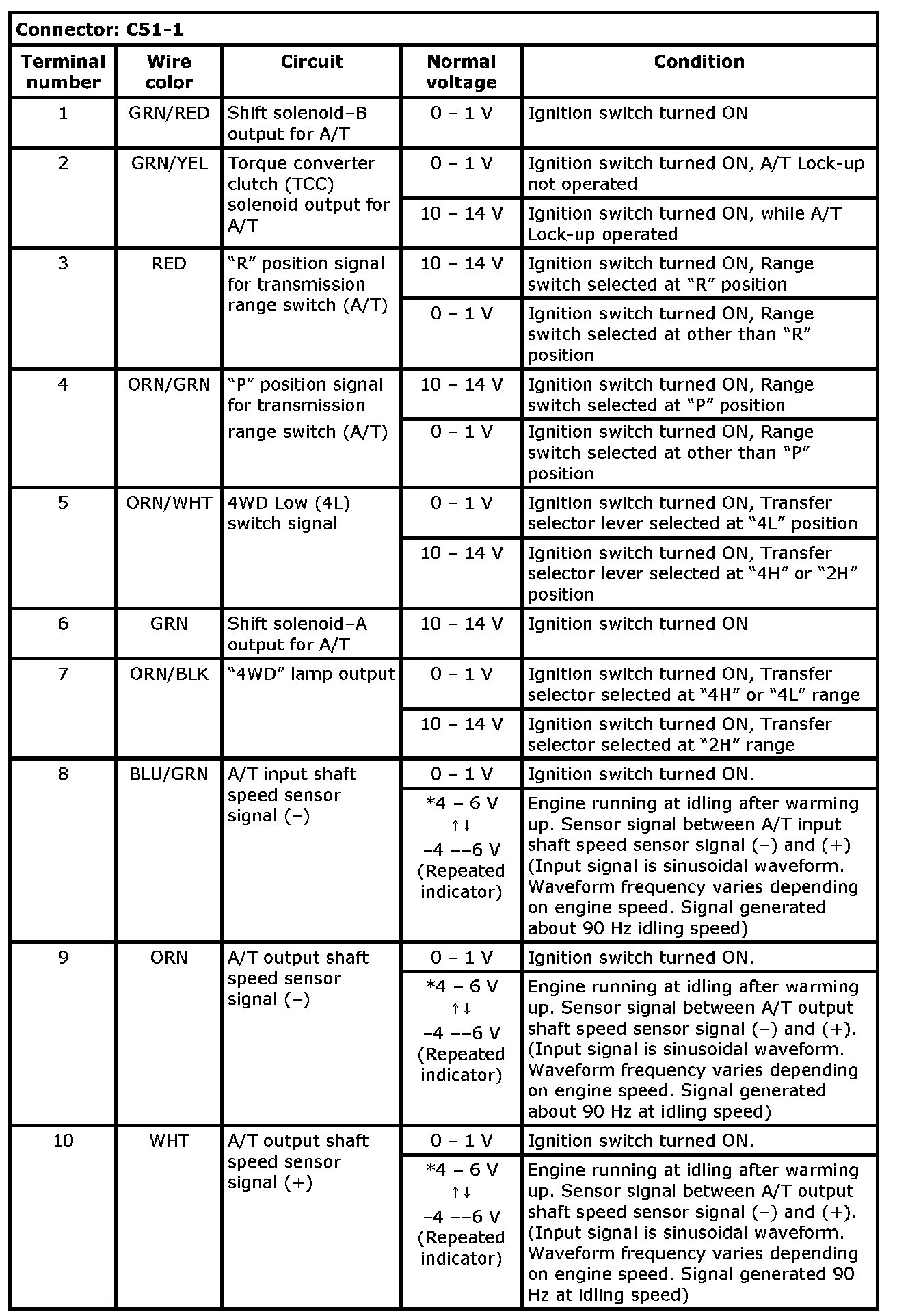
Ter. C51-1-1 - C51-1-10:
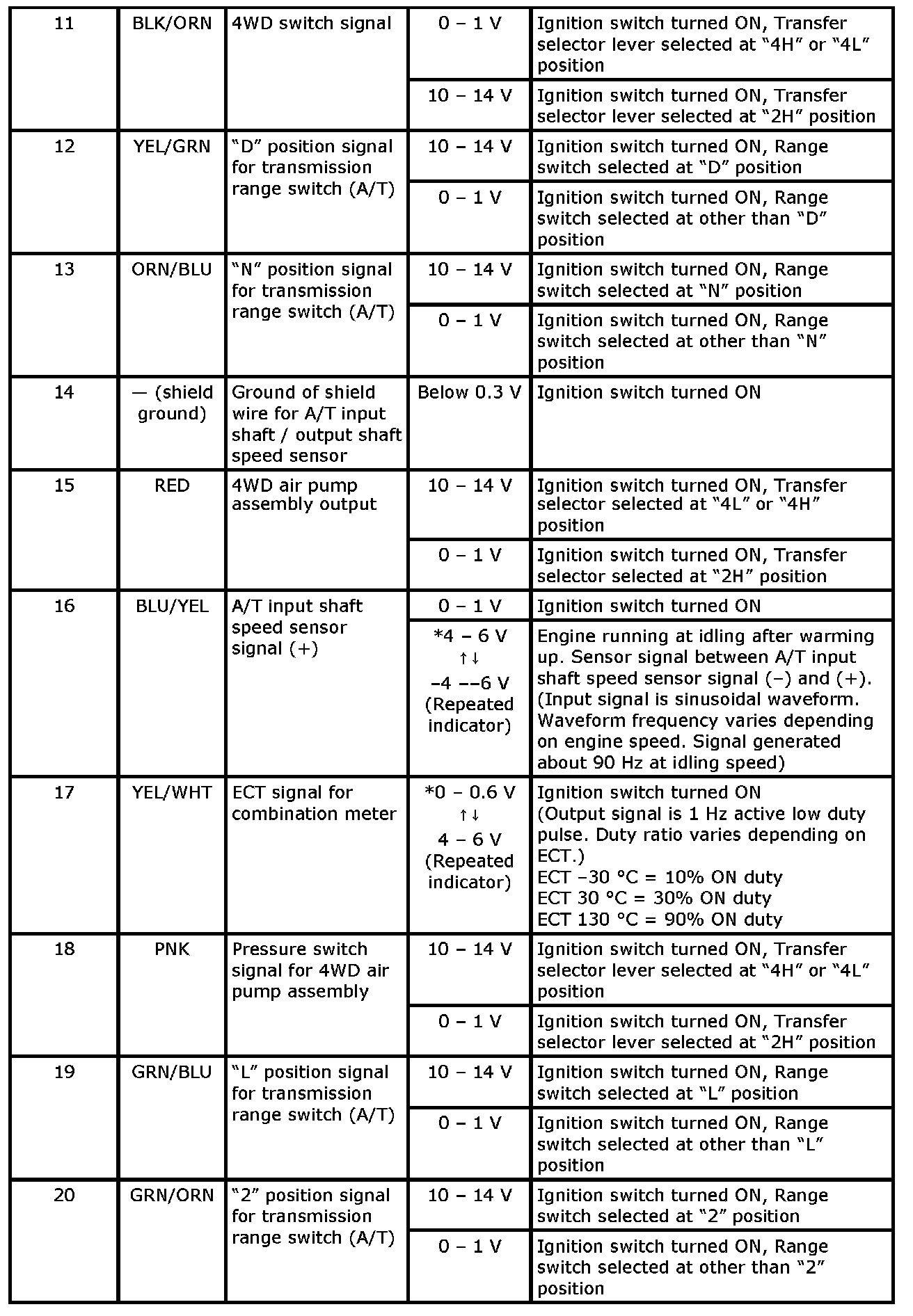
Ter. C51-1-11 - C51-1-20:
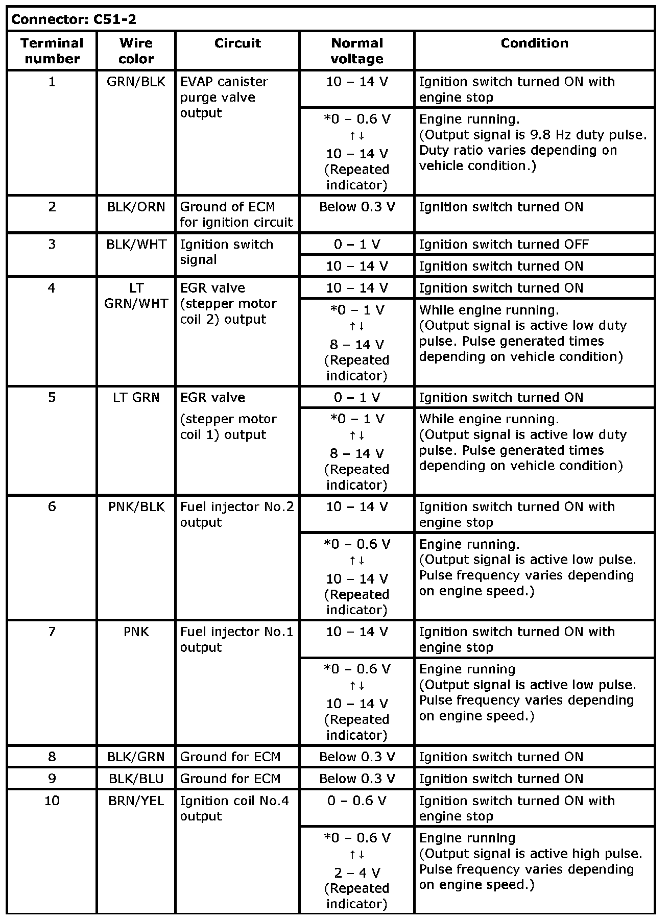
Ter. C51-2-1 - C51-2-10:
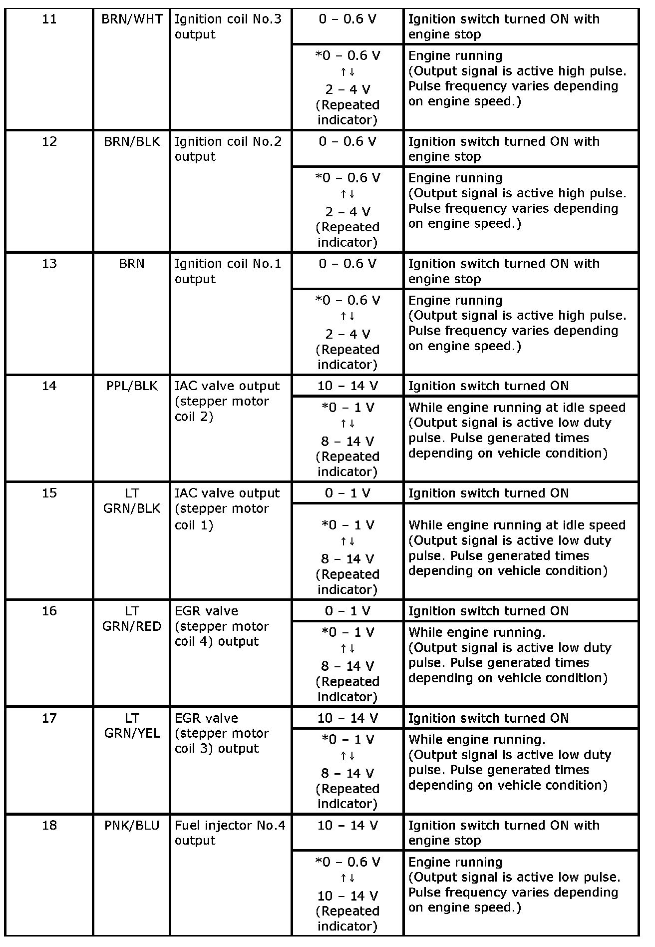
Ter. C51-2-11 - C51-2-18:
Ter. C51-2-19 - C51-2-28:
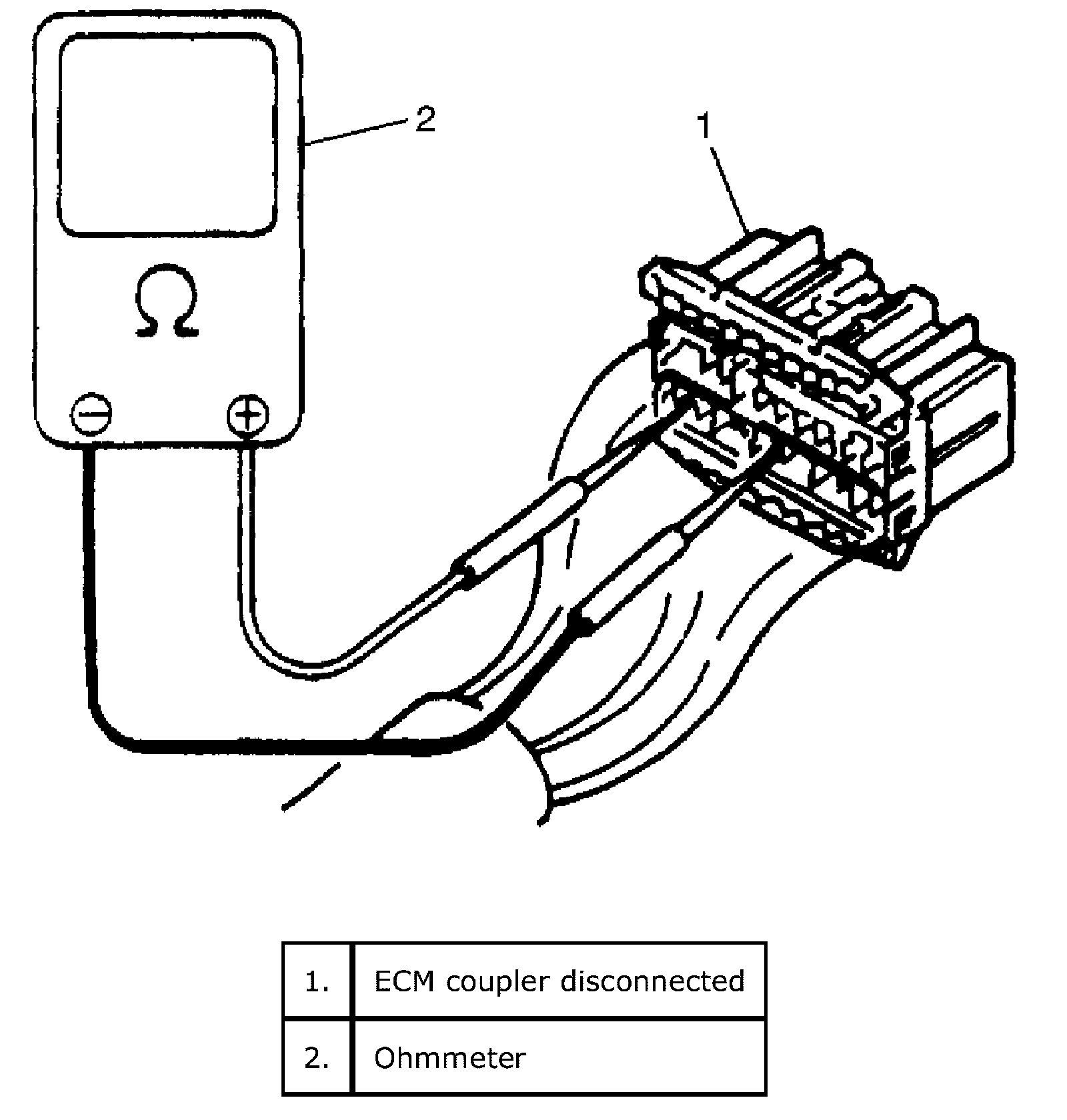
1. Remove ECM (PCM) cover from bracket.
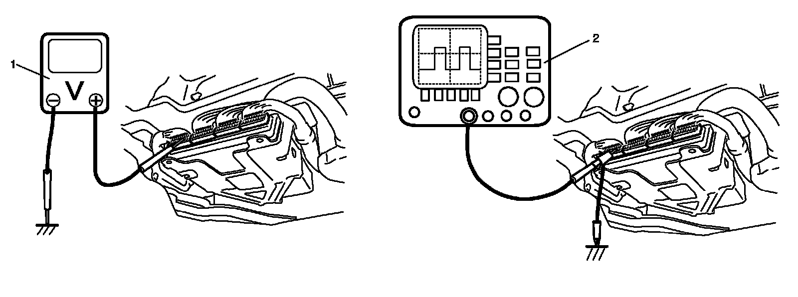
2. Check voltage at each terminal of couplers connected, using voltmeter (1) or oscilloscope.
NOTE:
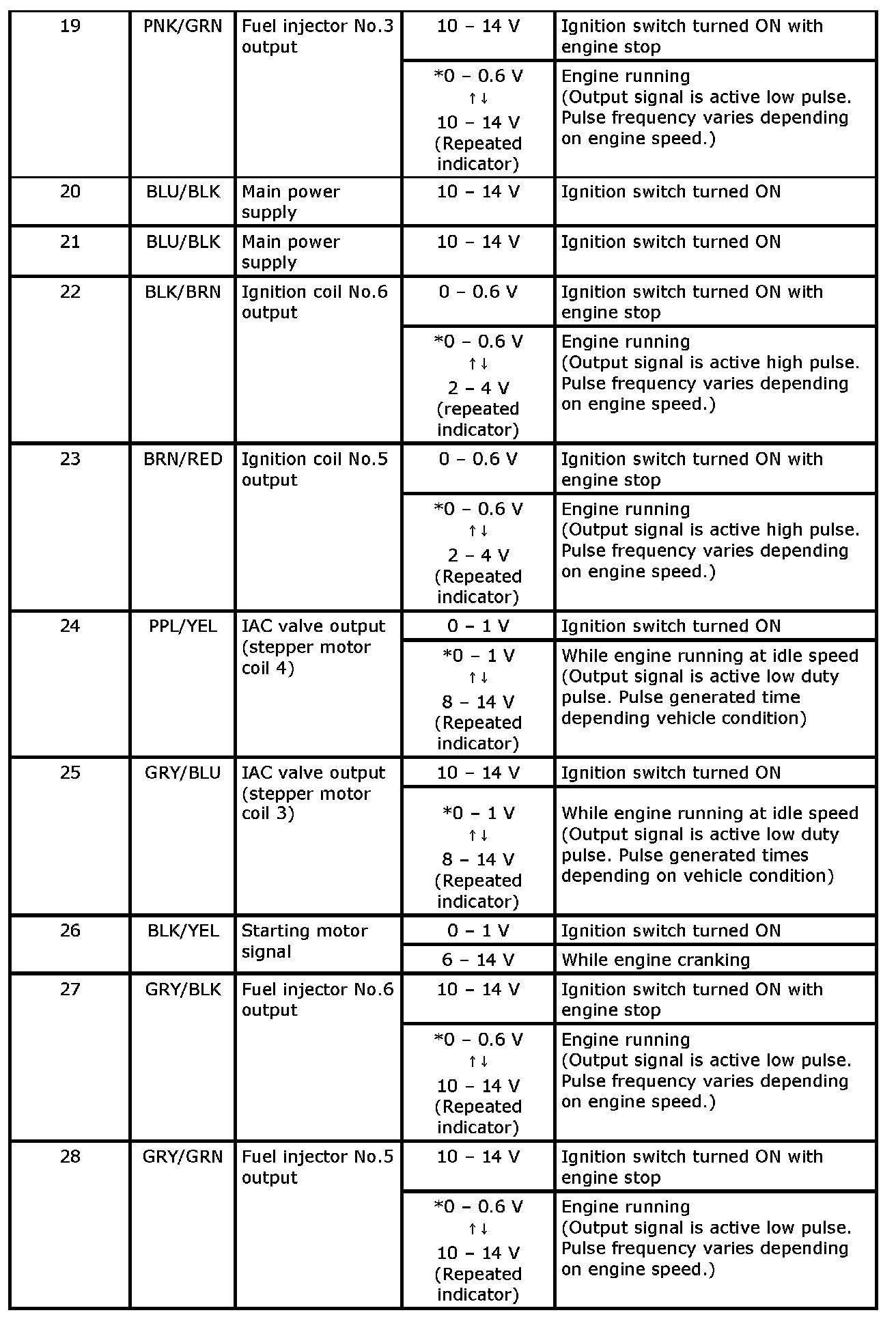
- As each terminal voltage is affected by the battery voltage, confirm that it is 11 V or more when ignition switch is turned ON.
- Voltage with asterisk (*) can not be measured by voltmeter because it is pulse signal.
Resistance Check
Resistance Table Specifications:
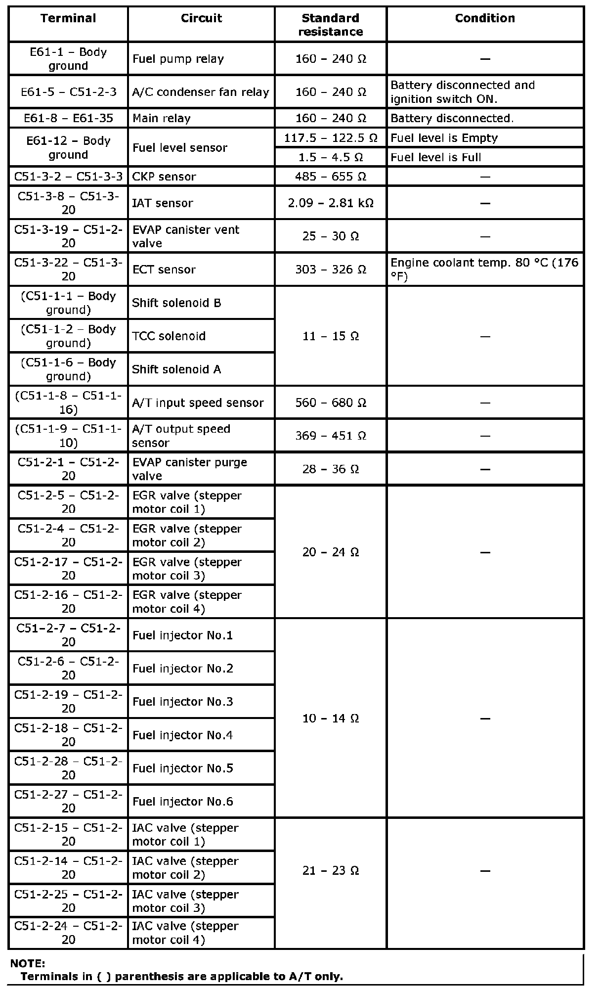
1. Disconnect ECM couplers from ECM with ignition switch OFF.
CAUTION: Never touch terminals of ECM itself or connect voltmeter or ohmmeter.
2. Check resistance between each pair of terminals of disconnected couplers as listed in the table.
CAUTION:
- Be sure to connect ohmmeter probe from wire harness side of coupler.
- Be sure to turn OFF ignition switch for this check.
- Resistance in table represents that when parts temperature is 20 °C (68 °F).