P0140
DTC P0140 Downstream Heated Oxygen Sensor Bank 1 No Activity DetectedWiring Diagram:
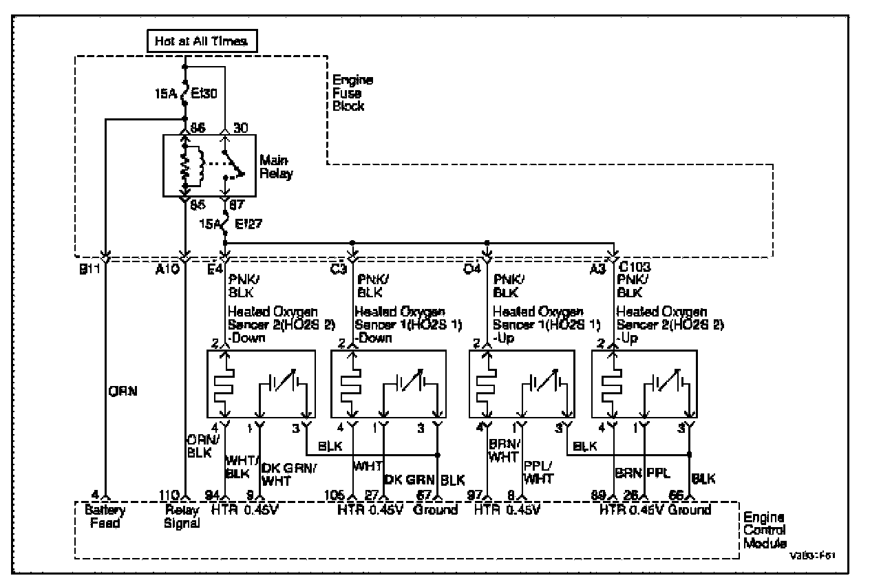
Circuit Description
The engine control module (ECM) supplies a voltage of about 0.45 V between the ECM terminals 27 and 67. The oxygen (O2) sensor varies the voltage within a range of about 1 V if the exhaust is rich, down to about 0.1 V if the exhaust is lean. The O2 sensor is like an open circuit and produces no voltage when it is below 360 °C (600 °F). An open O2 sensor circuit or a cold O2 sensor causes "open loop" operation.
Conditions for Setting the DTC
- 02 sensor operative.
- Nominal Heating phase.
- Fuel cut-off active.
- Integrated Mass Air Flow (MAF) since begin is greater than 40 g.
- No relevant DTCs are set.
- Battery voltage is higher than 10 V.
- HO2S signal voltage is higher than 0.0146 V during fuel cut-off phase.
Action Taken When the DTC Sets
- The Malfunction Indicator Lamp (MIL) will illuminate.
- The ECM will record operating conditions at the time the diagnostic fails. This information will be stored in the Freeze Frame and Failure Records buffers.
- A history DTC is stored.
Conditions for Clearing the MIL/DTC
- The MIL will turn off at the end of three (3) consecutive validation cycles in which the diagnostic runs without a fault.
- A history DTC will clear after 40 warm up cycles without a fault.
- DTC(s) can be cleared by using the scan tool.
Diagnostic Aids
Normal scan tool voltage varies between 0.15 to 8.5 mV while in Closed Loop. If DTC P0140 is intermittent, refer to Intermittents. Intermittents
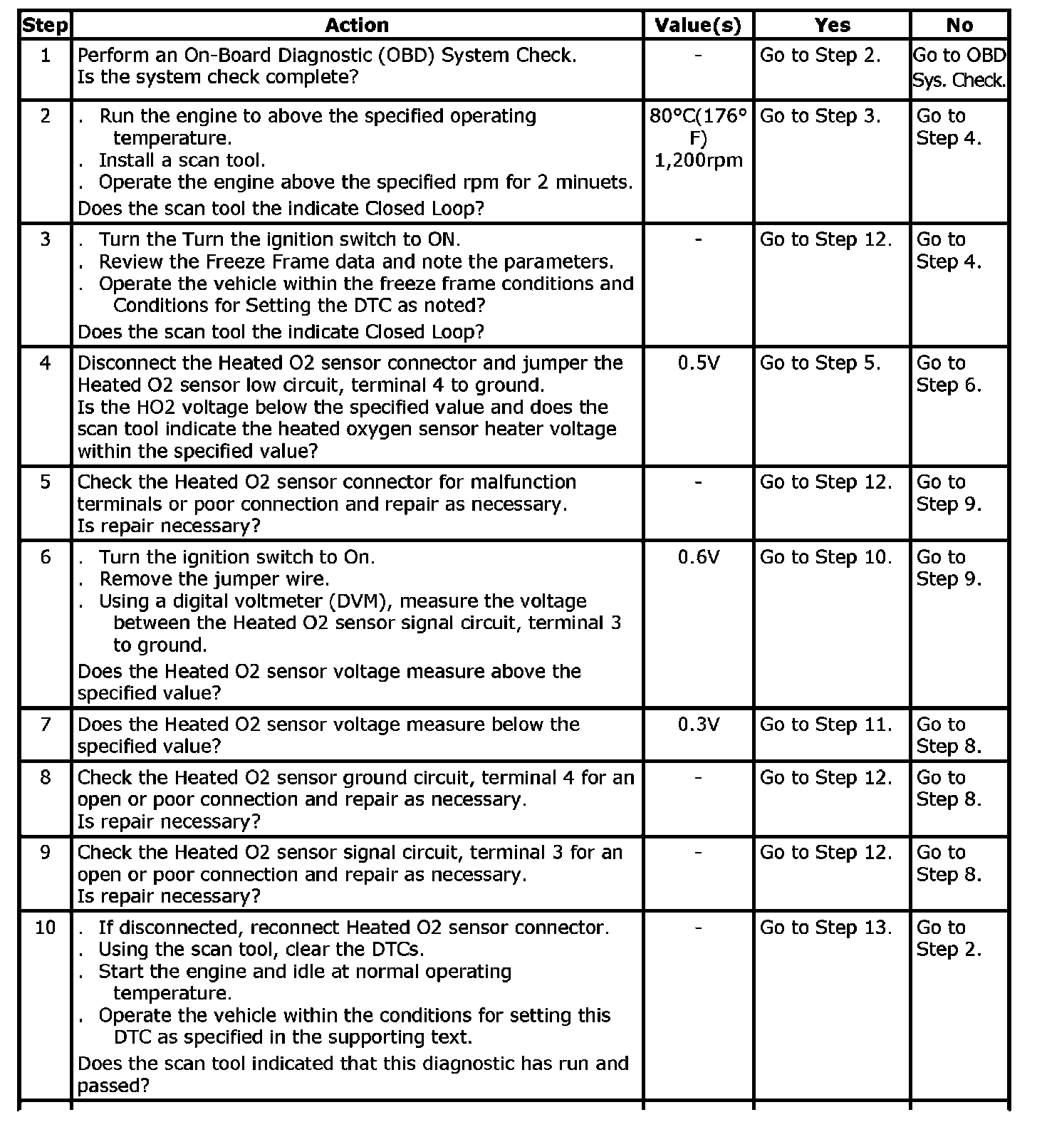
Step 1 - 10:
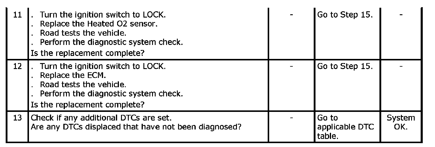
Step 11 - 13:
DTC P0140 - Downstream Heated Oxygen Sensor Bank 1 No Activity Detected