Base Braking Mode
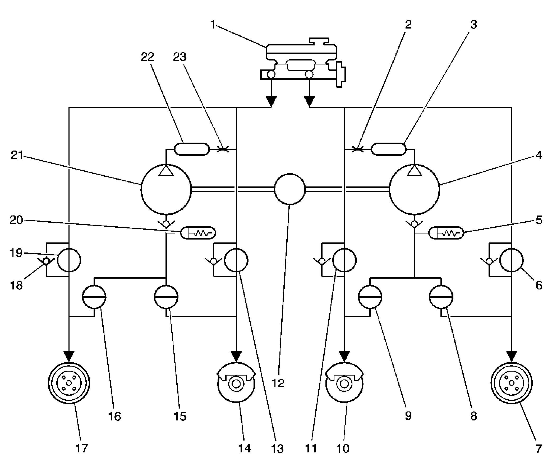
The baseline braking mode of the ABS modulator used in this vehicle is a diagonal split system. In this system, 1 master cylinder circuit supplies pressure to the right front and the left rear brakes. The other circuit supplies pressure to the left front and the right rear brakes. All valves in the hydraulic modulator are in their normal, non-energized positions as shown in the drawings found in the hydraulic diagram.
 Courtesy of GENERAL MOTORS CORP.
| Callout |
Component Name |
| 1 |
Master Cylinder |
| 2 |
Orifice |
| 3 |
Damper |
| 4 |
Positive Displacement Pump |
| 5 |
Accumulator |
| 6 |
Inlet Valve |
| 7 |
Right Rear Drum |
| 8 |
Outlet Valve |
| 9 |
Outlet Valve |
| 10 |
Left Front Caliper |
| 11 |
Inlet Valve |
| 12 |
Electric Motor |
| 13 |
Inlet Valve |
| 14 |
Right Front Caliper |
| 15 |
Outlet Valve |
| 16 |
Outlet Valve |
| 17 |
Left Rear Drum |
| 18 |
Check Valve |
| 19 |
Inlet Valve |
| 20 |
Accumulator |
| 21 |
Positive Displacement Pump |
| 22 |
Damper |
| 23 |
Orifice |
 Courtesy of GENERAL MOTORS CORP.
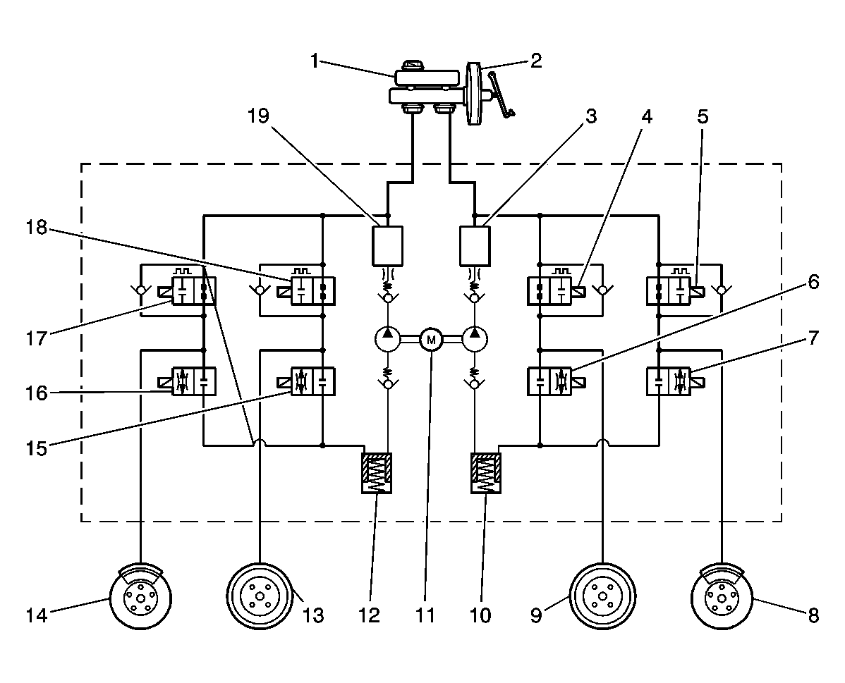
| Callout |
Component Name |
| 1 |
Reservoir |
| 2 |
Master Cylinder |
| 3 |
High Pressure Accumulator |
| 4 |
Inlet Valve |
| 5 |
Inlet Valve |
| 6 |
Outlet Valve |
| 7 |
Outlet Valve |
| 8 |
Left Front |
| 9 |
Right Rear |
| 10 |
Low Pressure Accumulator |
| 11 |
Motor |
| 12 |
Low Pressure Accumulator |
| 13 |
Left Rear |
| 14 |
Right Front |
| 15 |
Outlet Valve |
| 16 |
Outlet Valve |
| 17 |
Inlet Valve |
| 18 |
Inlet Valve |
| 19 |
High Pressure Accumulator |