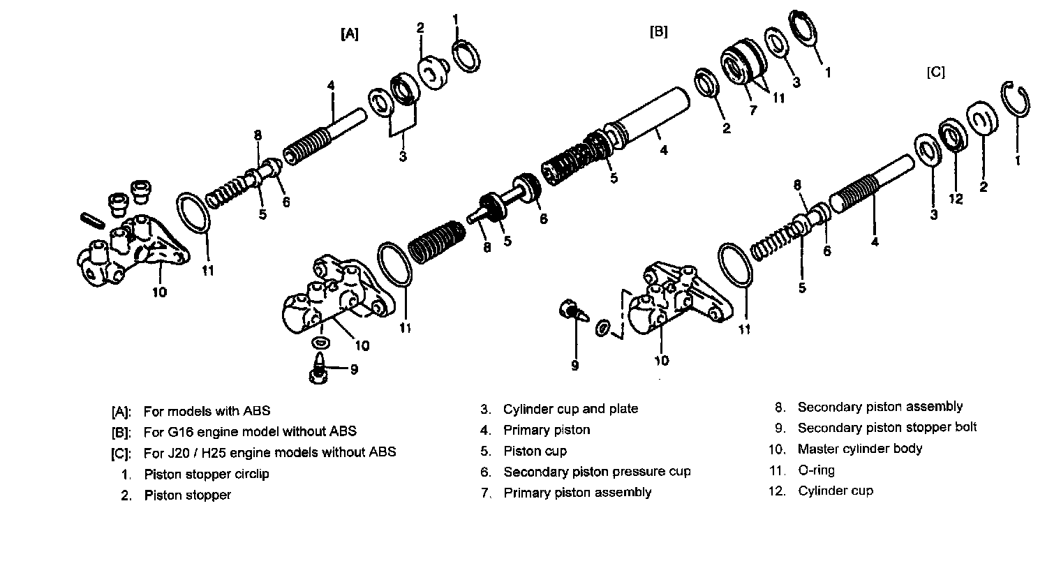
Master Cylinder Assembly Replacement
Removal
NOTE: Do not allow brake fluid to get on painted surfaces.
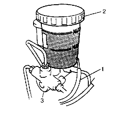
1. Disconnect reservoir lead wire (1) at coupler.
2. Clean around reservoir cap (2) and take out fluid with syringe or such.
3. Disconnect brake pipes from master cylinder (3) by the following procedure of each model.
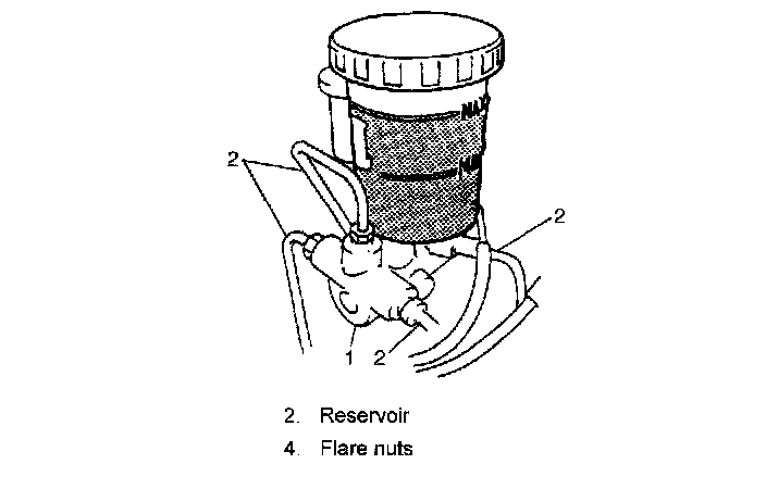
a) For vehicle without ABS:
i) Loosen flare nuts for master cylinder (1).
ii) Disconnect brake pipes (2) for master cylinder (1).
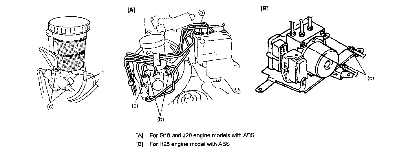
b) For G16 and J20 engine models with ABS:
i) Loosen flare nuts for master cylinder (1) and P valve (2).
ii) Disconnect brake pipes (3) for master cylinder (1) and P valve (2).
iii) Remove P valve (2).
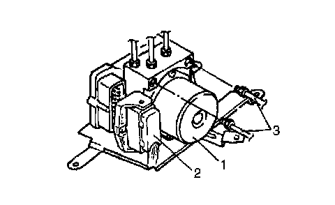
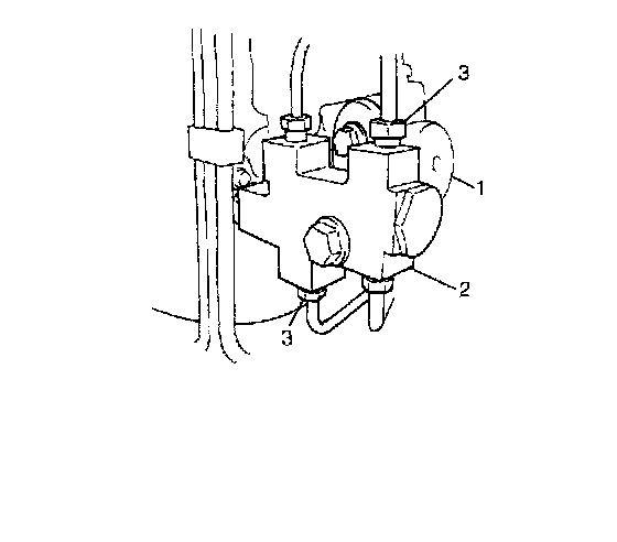
c) For H25 engine model with ABS.
i) Loosen flare nuts for master cylinder and ABS actuator (1) as shown in the figure.
ii) Disconnect ABS control module connector (2).
iii) Disconnect brake pipes (3) between master cylinder and ABS actuator (1).
4. Remove master cylinder with reservoir from brake booster.
Installation
NOTE: Adjust clearance between booster piston rod and primary piston with special tool.
1. Install master cylinder to brake booster.
2. For vehicle with ABS (G16/J20 engine models), install P valve to master cylinder.
3. Torque master cylinder attaching nuts to specified torque.
Tightening torque Master cylinder attaching nut (b): 13 Nm (1.3 kgf-m, 9.5 ft. lbs.)
4. Connect hydraulic lines to master cylinder, ABS actuator (if equipped) and P valve (if equipped) and torque flare nuts to specified torque.
Tightening torque Brake pipe flare nut (c): 16 Nm (1.6 kgf-m, 11.5 ft. lbs.)
5. Connect reservoir lead wire(1).
6. Fill reservoir with specified brake fluid.
7. After installing, check brake pedal play and bleed air from system.
8. Perform brake test and check each installed part for fluid leakage.