Diagnosis & Repair Procedure
- If engine system check has been performed, go to next step. If engine system check has not been performed, go to A4: ENGINE SYSTEM CHECK under SYSTEM TESTS.
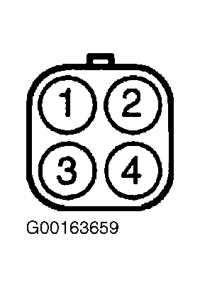
- Turn ignition off. Disconnect Bank 1 HO2S No. 1 4-pin harness connector. Bank 1 HO2S No. 1 is located in left exhaust pipe before catalytic convertor. Measure resistance between Bank 1 HO2S No. 1 pigtail connector terminal No. 3 (Green wire) and No. 4 (Blue wire). See Fig 1. Resistance should be 5.0-6.4 ohms at 68°F (20°C). If resistance is as specified, go to next step. If resistance is not as specified, replace HO2S. After repair, repeat DTC CONFIRMATION TEST .
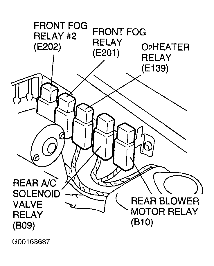
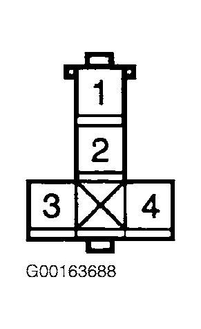
- Disconnect HO2S heater relay. HO2S heater relay is located on left fender well. See Fig 2. Turn ignition on. Measure voltage between ground and HO2S heater relay socket cavity No. 3 (Black/White wire). See Fig 3. Also, measure voltage between ground and HO2S heater relay socket cavity No. 1 (Blue/White wire). If voltage readings at both measurements is 10-14 volts, go to step 5. If voltage readings are not as specified, go to next step.
- Check for blown HO2S (15-amp) or IG METER (20-amp) fuses. Fuses are located in underhood fuse and relay box. If fuses are okay, check for open or short to ground in Black/White wire between IG METER fuse and HO2S heater relay. See WIRING DIAGRAMS
article. Also, check for open or short to ground in Blue/White wire between HO2S fuse and HO2S heater relay. If problem is found, repair as necessary. After repair, repeat DTC CONFIRMATION TEST .
- Turn ignition off. Install HO2S heater relay. Disconnect ECM 30-pin harness connector C51-2. ECM is located under instrument panel, behind glove box. See Figure. Measure voltage between ground and ECM harness connector C51-2 terminal No. 4 (Green wire). See Figure. If voltage reading is 10-14 volts, substitute a known good ECM, and repeat DTC CONFIRMATION TEST . If DTC does not reset, testing is complete. If voltage readings are not as specified, go to next step.
- Check for short to ground in Green wire between Bank 1 HO2S No. 1 and ECM. See WIRING DIAGRAMS
article. If no problem with wiring is found, replace HO2S heater relay. If problem persists after repairs, substitute a known good ECM, and repeat DTC CONFIRMATION TEST .
 Courtesy of SUZUKI OF AMERICA CORP.
 Courtesy of SUZUKI OF AMERICA CORP.
 Courtesy of SUZUKI OF AMERICA CORP.