Component Tests and General Diagnostics
Daytime Running Light (D.R.L) System On-Vehicle Inspection1. Apply parking brake and stop engine. With turned on lighting switch and operated dimmer switch, check headlights come on.
2. Start engine.
3. With released parking brake but apply foot brake, turn lighting switch at either "OFF" or "SMALL" position, check headlights come on.
4. With applied parking brake, check headlights go out.
5. If check result is OK in above step 1., 3. and 4., D.R.L. system is OK. If malfunction is found, go to next step 6..
6. Disconnect negative cable (-) at battery.
7. Disconnect D.R.L. controller coupler and connect negative cable at battery.
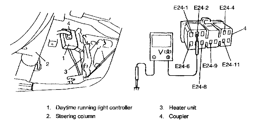
8. Check that the voltage and resistance between the following terminals are specifications. If check result is not satisfactory, repair.
Daytime running light system circuit specification
Terminals "E2-1" and ground (Lighting switch OFF): No continuity
Terminals "E2-1" and ground (Lighting switch ON): Continuity
Terminals "E2-4" and ground (Do not apply parking brake): No continuity
Terminals "E2-4" and ground (Apply parking brake): Continuity
Terminals "E2-6" and ground (Lighting switch OFF): No continuity
Terminals "E2-6" and ground (Lighting switch ON): Continuity
Terminals "E2-8" and ground: Continuity
Terminals "E2-2" and ground (Engine stop): 0 V
Terminals "E2-2" and ground (Engine run): 0 - 14 V
Terminals "E2-9" and ground (Ignition switch OFF): 0 V
Terminals "E2-9" and ground (Ignition switch ON): 0 - 14 V
Terminals "E2-11" and ground (Ignition switch OFF): 0 V
Terminals "E2-11" and ground (Ignition switch ON): 0 - 14 V
9. If check result of Step 8 is OK, replace controller and recheck.