Cylinder Block Assembly
Cylinders^ Inspect cylinder walls for scratches, roughness, or ridges, which indicate excessive wear. If cylinder bore is very rough or deeply scratched, or ridged, rebore cylinder and use oversize piston.
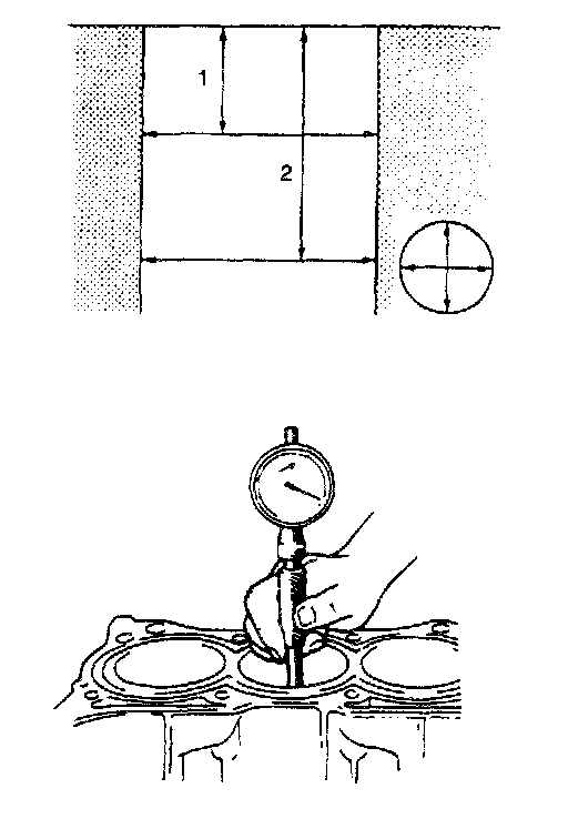
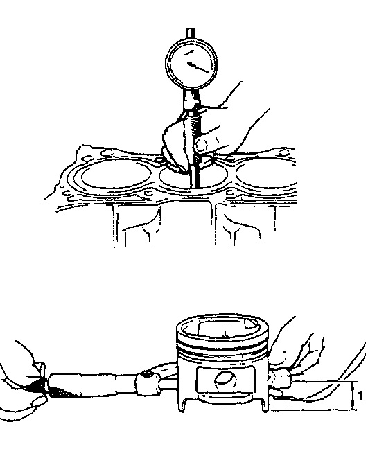
^ Using a cylinder gauge, measure cylinder bore in thrust and axial directions at 2 positions as shown in the figure. If any of the following conditions is noted, rebore cylinder.
- Cylinder bore dia. exceeds limit.
- Difference of measurements at 2 positions exceeds taper limit.
- Difference between thrust and axial measurements exceeds out-of-round limit.
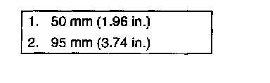
Cylinder bore dia. limit: 75.15 mm (2.9586 inch)
Taper and out-of-round limit: 0.10 mm (0.0039 inch)
NOTE: If any one of four cylinders has to be rebored, rebore all 4 to the same next oversize. This is necessary for the sake of uniformity and balance.
Pistons
^ Inspect piston for faults, cracks or other damaged. Damaged or faulty piston should be replaced.
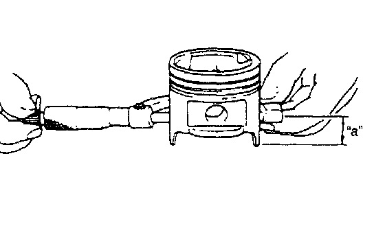
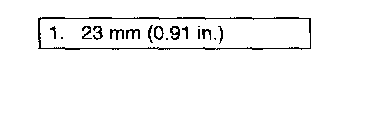
^ Piston diameter:
As shown in the figure, piston diameter should be measured at a position "a" 23 mm (0.91 inch) from piston skirt end in the direction perpendicular to piston pin.
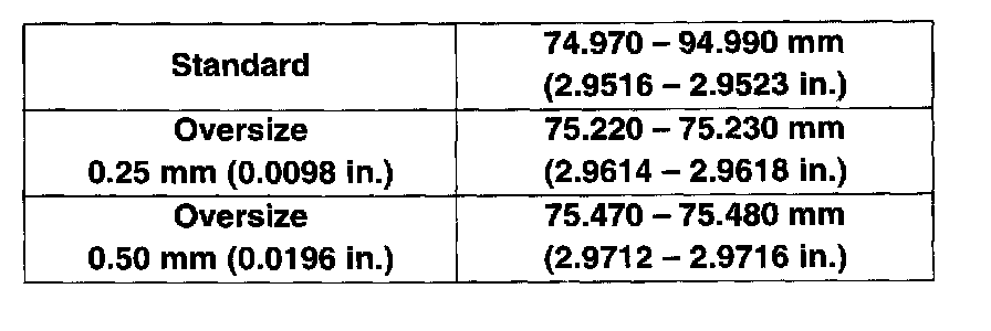
Piston diameter:
Piston clearance:
Measure cylinder bore diameter and piston diameter to find their difference, which is piston clearance. Piston clearance should be within specification as given below. If it is out of specification, rebore cylinder and use oversize piston.
Piston clearance: 0.02 - 0.04 mm (0.0008 - 0.0015 inch)
NOTE: Cylinder bore diameters used here are measured in thrust direction at 2 positions.
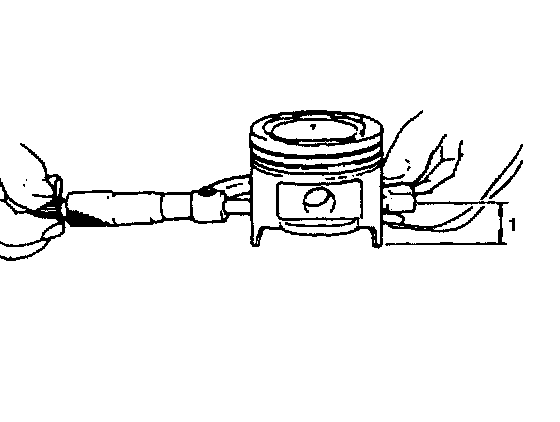
Ring groove clearance:
Before checking, piston grooves must be clean, dry and free of carbon.
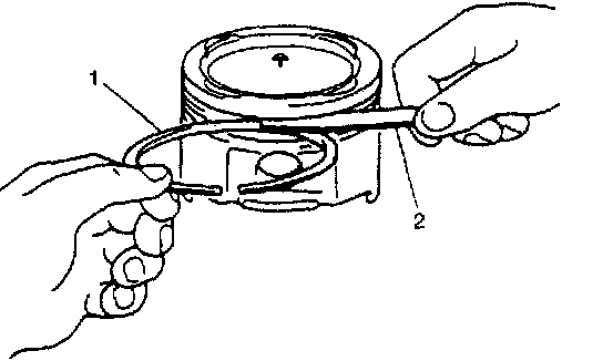
Fit new piston ring into piston groove, and measure clearance between ring (1) and ring land by using thickness gauge (2). If clearance is out of specification, replace piston.
Ring groove clearance:
Top: 0.03 - 0.07 mm (0.0012 - 0.0027 inch)
2nd: 0.02 - 0.06 mm (0.0008 - 0.0023 inch)
Piston Pin
^ Check piston pin, connecting rod small end bore and piston bore for wear or damage, paying particular attention to condition of small end bore bush. If pin, connecting rod small end bore or piston bore is badly worn or damaged, replace pin, connecting rod or piston.
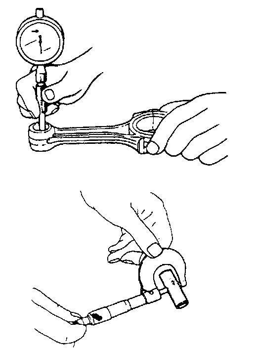
^ Piston pin clearance: Check piston pin clearance in small end. Replace connecting rod if its small end is badly worn or damaged or if measured clearance exceeds limit.
Piston clearance in small end:
Standard: 0.003 - 0.014 mm (0.0001 - 0.0006 inch)
Limit: 0.05 mm (0.0020 inch)
Small-end bore: 19.003 - 19.011 mm (0.7482 - 0.7486 inch)
Piston pin dia.: 18.997 - 19.000 mm (0.7479 - 0.7480 inch)
Piston Rings
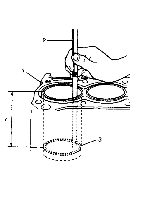
To measure end gap, insert piston ring into cylinder bore, and then measure the gap by using thickness gauge. If measured gap is out of specification, replace ring.
NOTE: Decarbon and clean top of cylinder bore before inserting piston ring.
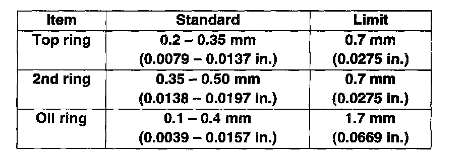
Piston ring end gap
Connecting Rod
Big-end side clearance
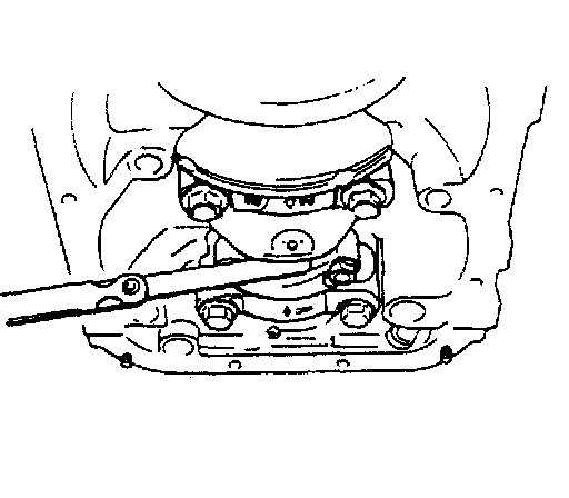
Check big-end of connecting rod for side clearance, with rod fitted and connected to its crank pin in the normal manner. If measured clearance is found to exceed its limit, replace connecting rod.
Big-end side clearance:
Standard: 0.10 - 0.25 mm (0.0039 - 0.0098 inch)
Limit: 0.35 mm (0.0137 inch)
Connecting rod alignment
Mount connecting rod on aligner to check it for bow and twist and, if limit is exceeded, replace it.
Connecting rod alignment:
Limit on bow: 0.05 mm (0.0020 inch)
Limit on twist: 0.10 mm (0.0039 inch)
Crank Pin and Connecting Rod Bearings
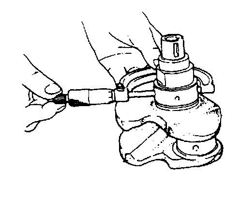
^ Inspect crank pin for uneven wear or damage. Measure crank pin for out-of-round or taper with a micrometer. If crank pin is damaged, or out-of-round or taper is out of limit, replace crankshaft or regrind crank pin rend check rod bearing clearance.
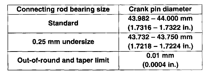
Crank pin specification:
Rod bearing:
Inspect bearing shells for signs of fusion, pitting, burn or flaking and observe contact pattern. Bearing shells found in defective condition must be replaced.
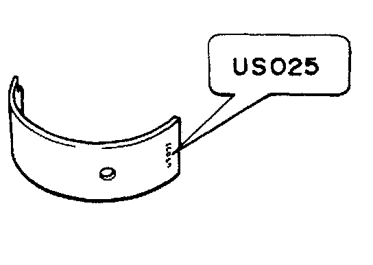
Two kinds of rod bearing are available; standard size bearing and 0.25 mm undersize bearing. To distinguish them, 0. 25 mm undersize bearing has the stamped number (US025) on its backside as indicated in figure, but standard size one has no number.
Rod bearing clearance:
1. Before checking bearing clearance, clean bearing and crank pin.
2. Install bearing in connecting rod and bearing cap.
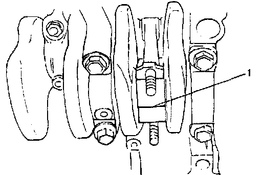
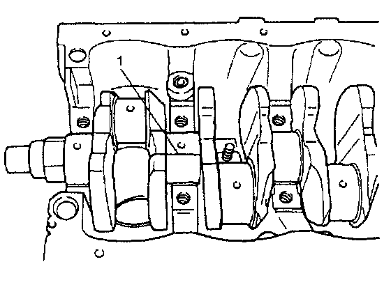
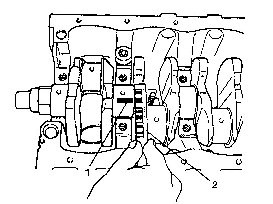
3. Place a piece of gaging plastic (1) to full width of crank pin as contacted by bearing (parallel to crankshaft), avoiding oil hole.
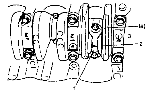
4. Install rod bearing cap to connecting rod.
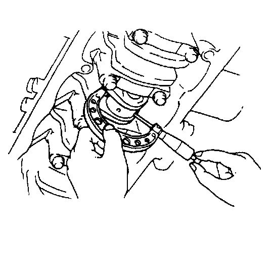
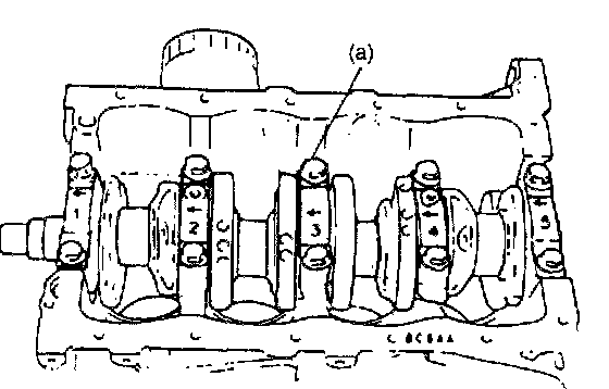
When installing cap (1), be sure to point arrow mark (2) on cap (1) to crankshaft pulley side (3) as shown in the figure. After applying engine oil to rod bolts, tighten cap nuts to specified torque. DO NOT turn crankshaft with gaging plastic installed.
Tightening torque
Rod bearing cap nut (a): 35 Nm (3.5 kg-m, 25.5 ft. lbs.)
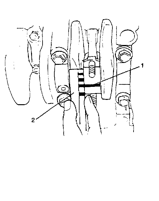
5. Remove cap and using a scale (2) on gaging plastic (1) envelope, measure gaging plastic width at the widest point (clearance).
If clearance exceeds its limit, use a new standard size bearing and remeasure clearance.
Connecting rod Bearing clearance
Standard: 0.020 - 0.050 mm (0.0008 - 0.0019 inch)
Limit: 0.080 mm (0.0031 inch)
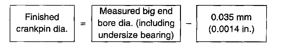
6. If clearance can not be brought to within its limit even by using a new standard size bearing, replace crankshaft or regrind crankpin to undersize as follows.
- Install 0.25 mm undersize bearing to connecting rod big end.
- Measure bore diameter of connecting rod big end.
- Regrind crankpin to following finished diameter.
- Confirm that bearing clearance is within above standard value.
Crankshaft
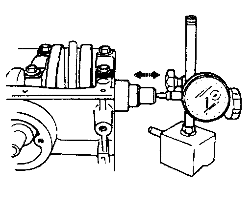
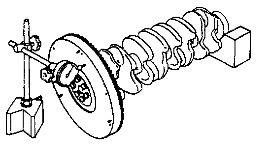
Crankshaft runout
Using a dial gauge, measure runout at center journal. Rotate crankshaft slowly. If runout exceeds its limit, replace crankshaft.
Crankshaft runout:
Limit: 0.06 mm (0.0023 inch)
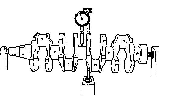
Crankshaft thrust play
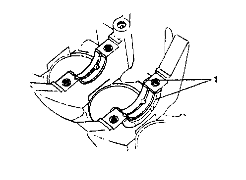
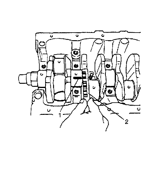
Measure this play with crankshaft set in cylinder block in the normal manner, that is, with thrust bearing (1) and journal bearing caps installed.
Use a dial gauge to read displacement in axial (thrust) direction of crankshaft.
If its limit is exceeded, replace thrust bearing with new standard one or oversize one to obtain standard thrust play.
Crankshaft thrust play
Standard: 0.11 - 0.31 mm (0.0044 - 0.0122 inch)
Limit: 0.38 mm (0.0149 inch)
Thickness of crankshaft thrust bearing
Standard: 2.500 mm (0.0984 inch)
Oversize (0.125 mm (0.0049 inch)): 2.563 mm (0.1009 inch)
Out-of-round and taper (uneven wear) of journals
An unevenly worn crankshaft journal shows up as a difference in diameter at a cross section or along its length (or both). This difference, if any, is determined by taking micrometer readings.
If any one of journals is badly damaged or if amount of uneven wear in the sense explained above exceeds its limit, regrind or replace crankshaft.
Crankshaft out-of-round and taper:
Limit: 0.01 mm (0.0004 inch)
Main Bearings
General information
^ Service main bearings are available in standard size and 0.25 mm (0.0098 inch) undersize, and each of them has 5 kinds of bearings differing in tolerance.
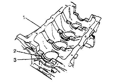
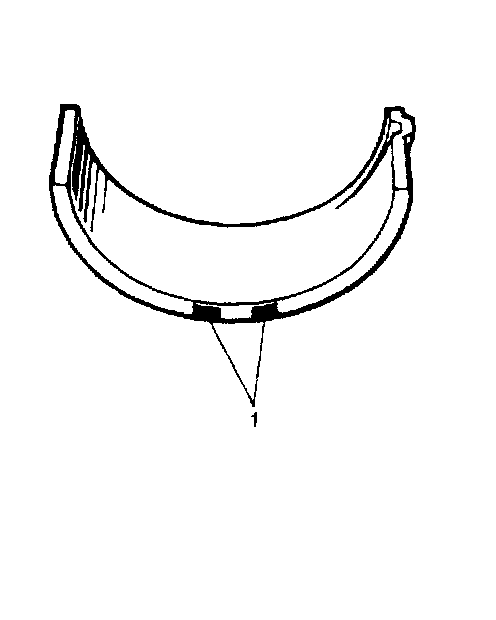
^ Upper half of bearing (2) has oil groove (3) as shown in the figure. Install this half with oil groove (3) to cylinder block (1).
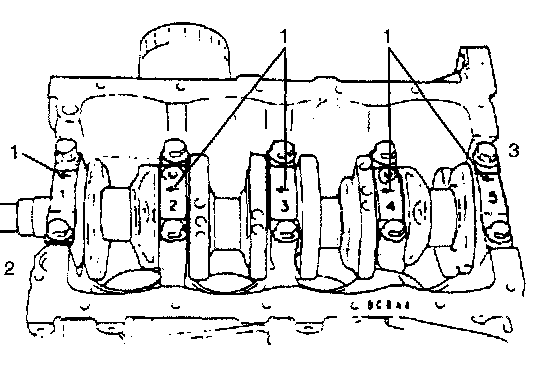
^ On each main bearing cap, arrow mark (1) and number are embossed as shown in the figure. When installing each bearing cap to cylinder block, point arrow mark (1) toward crankshaft pulley side (2) and install each cap from that side (3) to flywheel side in ascending order of numbers "1", "2", "3", "4" and "5". Tighten cap bolts to specified torque.
Main bearing clearance
Check clearance by using gaging plastic (1) according to the following procedure.
1. Remove bearing caps.
2. Clean bearings and main journals.
3. Place a piece of gaging plastic to full width of bearing (parallel to crankshaft) on journal, avoiding oil hole.
4. Install bearing cap and evenly toque cap bolts to specified torque.
Bearing cap must be torqued to specification in order to assure proper reading of clearance.
Tightening torque
Main bearing cap bolt (a): 54 Nm (5.4 kg-m, 39.0 ft. lbs.)
NOTE: Do not rotate crankshaft while gaging plastic is installed.
5. Remove cap and using scale (2) on gaging plastic (1) envelope, measure gaging plastic width at its widest point. If clearance exceeds its limit, replace bearing. Always replace both upper and lower inserts as a unit.
A new standard bearing may produce proper clearance. If not, it will be necessary to regrind crankshaft journal for use of 0.25 mm undersize bearing.
After selecting new bearing, recheck clearance.
Main bearing clearance:
Standard: 0.016 - 0.036 mm (0.0006 - 0.0014 inch)
Limit: 0.060 mm (0.0023 inch)
Selection of main bearings
^ STANDARD BEARING:
If bearing is in malcondition, or bearing clearance is out of specification, select a new standard bearing according to the following procedure and install it.
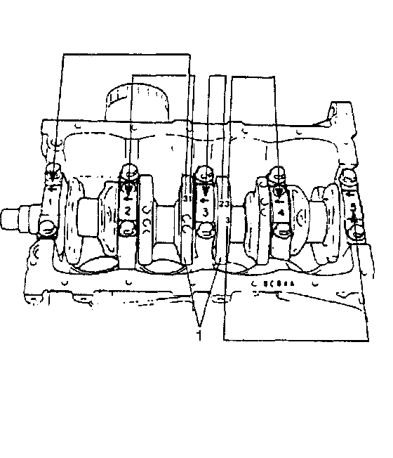

1. First check journal diameter by using the following procedure.
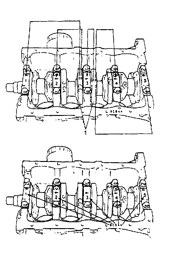
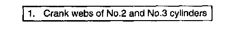
As shown in the figure, crank webs of No. 2 and No. 3 cylinders have 5 stamped numerals.
Three kinds of numerals ("1", "2" and "3") represent the following journal diameters.
The first, second, third, fourth and fifth (left to right) stamped numerals represent journal diameters at bearing caps "1", "2", "3", "4" and "5" respectively.
For example, in the figure, the first (left most) numeral "3" indicates that journal dia. at bearing cap "1" is within 51.982 - 51.988 mm, and second one "1" indicate that journal dia. at cap "2" is within 51.994 - 52.000 mm.
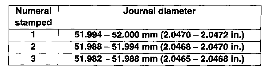
Journal diameter specification:
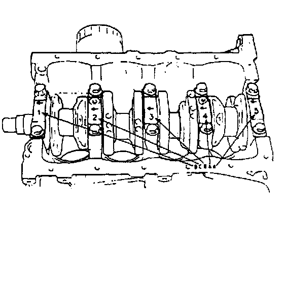
2. Next, check bearing cap bore diameter without bearing. On mating surface of cylinder block, 4 alphabets are stamped as shown in the figure.
3 kinds of alphabets ("A", "B" and "C") represent the following cap bore diameters.
The first, second, third, fourth and fifth (left to right) stamped alphabets represent cap bore diameters of bearing caps "1", "2", "30", "4" and "5", respectively.
For example, in the figure, the first (left most) alphabet "B" indicates that cap bore dia. of bearing cap "1" is within 56.006 - 56.012 mm, and the fifth (right most) alphabet "A" indicates that cap bore dia. of cap "5" is within 56.000 - 56.006 mm.
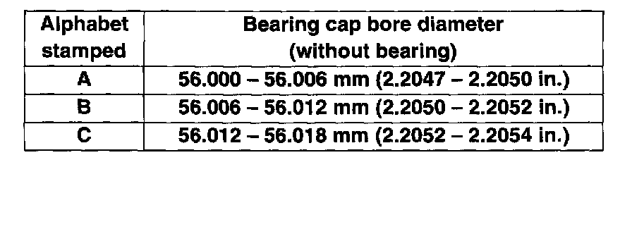
Main bearing cap bore diameter
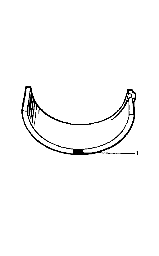
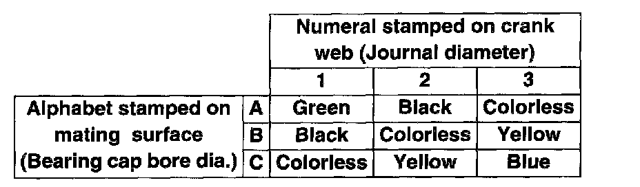
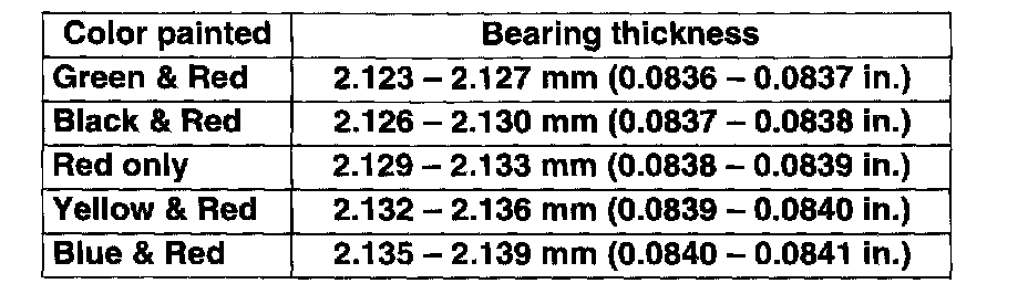
3. There are 5 kinds of standard bearings differing in thickness. To distinguish them, they are painted in the following colors at the position as shown in the figure.
Each color indicates the following thickness at the center of bearing.
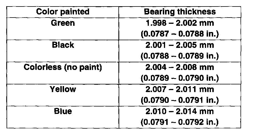
Main bearing thickness
4. From numerals stamped on crank webs of No. 2 and No. 3 cylinders and the alphabets stamped on mating surface of cylinder block, determine new standard bearing to be installed to journal.
For example, if numeral stamped on crank web is "1" and alphabet stamped on mating surface is "B", install a new standard bearing painted in "Black" to its journal.
New standard bearing specification:
5. Using gaging plastic (1) and scale (2), check bearing clearance with newly selected standard bearing.
If clearance still exceeds its limit, use next thicker bearing and recheck clearance.
6. When replacing crankshaft or cylinder block due to any reason, select new standard bearings to be installed by referring to numerals stamped on new crankshaft or alphabets stamped on mating surface of new cylinder block.
UNDERSIZE BEARING (0.25 mm)

0.25 mm undersize bearing is available, in 5 kinds varying in thickness.
To distinguish them, each bearing is painted in the following colors at such position as shown in the figure.
Each color represents the following thickness at the center of bearing.
Undersize main bearing thickness
If necessary, regrind crankshaft journal and select under-size bearing to use with it as follows.
1. Regrind journal to the following finished diameter.
Finished journal diameter: 51.732 - 51.750 mm (2.0367 - 2.0373 inch)
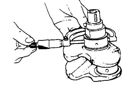
2. Using micrometer, measure reground journal diameter. Measurement should be taken in 2 directions perpendicular to each other in order to check for out-of-round.
3. Using journal diameter measured above and alphabets stamped on mating surface of cylinder block, select an undersize bearing. Check bearing clearance with newly selected undersize bearing.
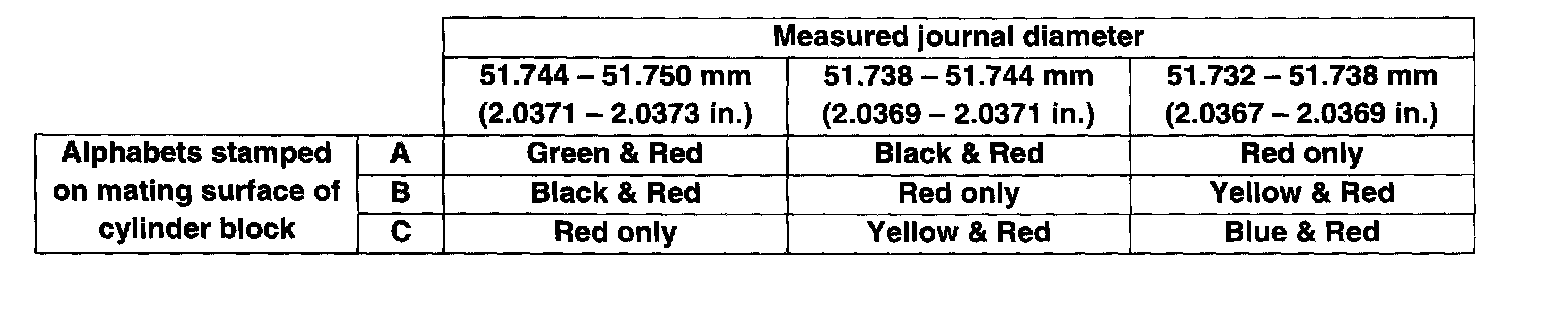
Undersize bearing specification:
Flywheel
^ If ring gear is damaged, cracked or worn, replace flywheel.
^ If the surface contacting clutch disc is damaged, or excessively worn, replace flywheel.
^ Check flywheel for face runout with dial gauge. If runout exceeds its limit, replace flywheel.
Flywheel runout:
Limit: 0.2 mm (0.0078 inch)
Cylinder Block
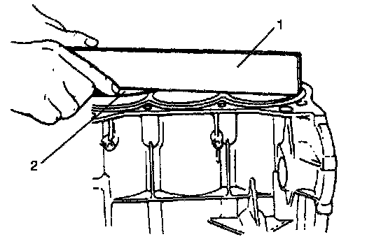
^ Distortion of gasketed surface
Using straightedge (1) and thickness gauge (2), check gasketed surface for distortion and, if flatness exceeds its limit, correct it.
Cylinder block distortion:
Standard: 0.03 mm (0.0012 inch)
Limit: 0.06 mm (0.0024 inch)
^ Honing or reboring cylinders
1. When any cylinder needs reboring, all other cylinders must also be rebored at the same time.
2. Select oversized piston according to amount of cylinder wear.
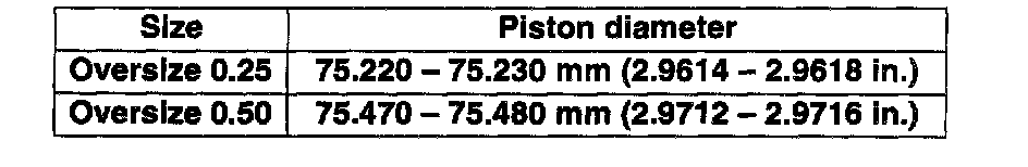
Oversize piston specification:

3. Using micrometer, measure piston diameter.
4. Calculate cylinder bore diameter to be rebored.
D = A + B - C
D: Cylinder bore diameter to be rebored.
A: Piston diameter as measured.
B: Piston clearance = 0.02 - 0.04 mm (0.0008 - 0.0015 inch)
C: Allowance for honing = 0.02 mm (0.0008 inch)
5. Rebore and hone cylinder to calculated dimension.
NOTE: Before reboring, install all main bearing caps in place and tighten to specification to avoid distortion of bearing bores.
6. Measure piston clearance after honing.