Diagnosis & Repair Procedure
- Check for DTC P0340. See RETRIEVING DIAGNOSTIC TROUBLE CODES
under SELF-DIAGNOSTIC SYSTEM. If DTC is not set, go to next step. If DTC is set, go to DTC P0340: CAMSHAFT POSITION (CMP) SENSOR CIRCUIT MALFUNCTION
.
- Perform DTC CONFIRMATION TEST
. If DTC P0335 is set, go to next step. If DTC P0335 is not set, problem is intermittent. System is okay at this time. See INTERMITTENTS
TROUBLE SHOOTING - NO CODES article.
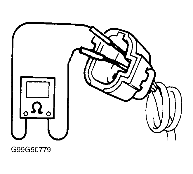
- Turn ignition off. Disconnect ECM (PCM) 26-pin connector C51-3. Measure resistance between ECM (PCM) 26-pin harness connector C51-3 terminals No. 2 (Orange/Black wire) and No. 3 (White/Blue wire). See Figure
. If resistance is 484-656 ohms at 68°F (20°C), go to step 5
. If resistance is not 484-656 ohms at 68°F (20°C), go to next step.
- Disconnect CKP sensor connector. Measure resistance between CKP sensor terminals No. 2 (Orange/Black wire) and No. 3 (White/Blue wire). See Fig 1
. If resistance is 484-656 ohms at 68°F (20°C), repair short or open in White/Blue wire or Orange/Black wire between CKP sensor and ECM (PCM) 26-pin connector C51-3. See ENGINE PERFORMANCE
in SYSTEM WIRING DIAGRAMS article in ELECTRICAL. Repair as necessary and go to DTC CONFIRMATION TEST
. If resistance is not 484-656 ohms at 68°F (20°C), replace CKP sensor and go to DTC CONFIRMATION TEST
.
- Check CKP sensor installation and condition of teeth on crankshaft. Repair as necessary and go to DTC CONFIRMATION TEST
. If CKP sensor and crankshaft are okay, check for poor terminal contact at ECM (PCM) 26-pin connector C51-3. If poor terminal contact is found, repair as necessary and go to DTC CONFIRMATION TEST
. If terminal contact is okay, check for short between White/Blue wire and Orange/Black. See ENGINE PERFORMANCE
in SYSTEM WIRING DIAGRAMS article in ELECTRICAL. Repair as necessary and go to DTC CONFIRMATION TEST
. If wires are okay, replace ECM (PCM) and go to DTC CONFIRMATION TEST
.
 Courtesy of SUZUKI OF AMERICA CORP.