Diagnosis & Repair Procedure
- If engine system check has been performed, go to next step. If engine system check has not been performed, go to A4: ENGINE SYSTEM CHECK
under SYSTEM TESTS.
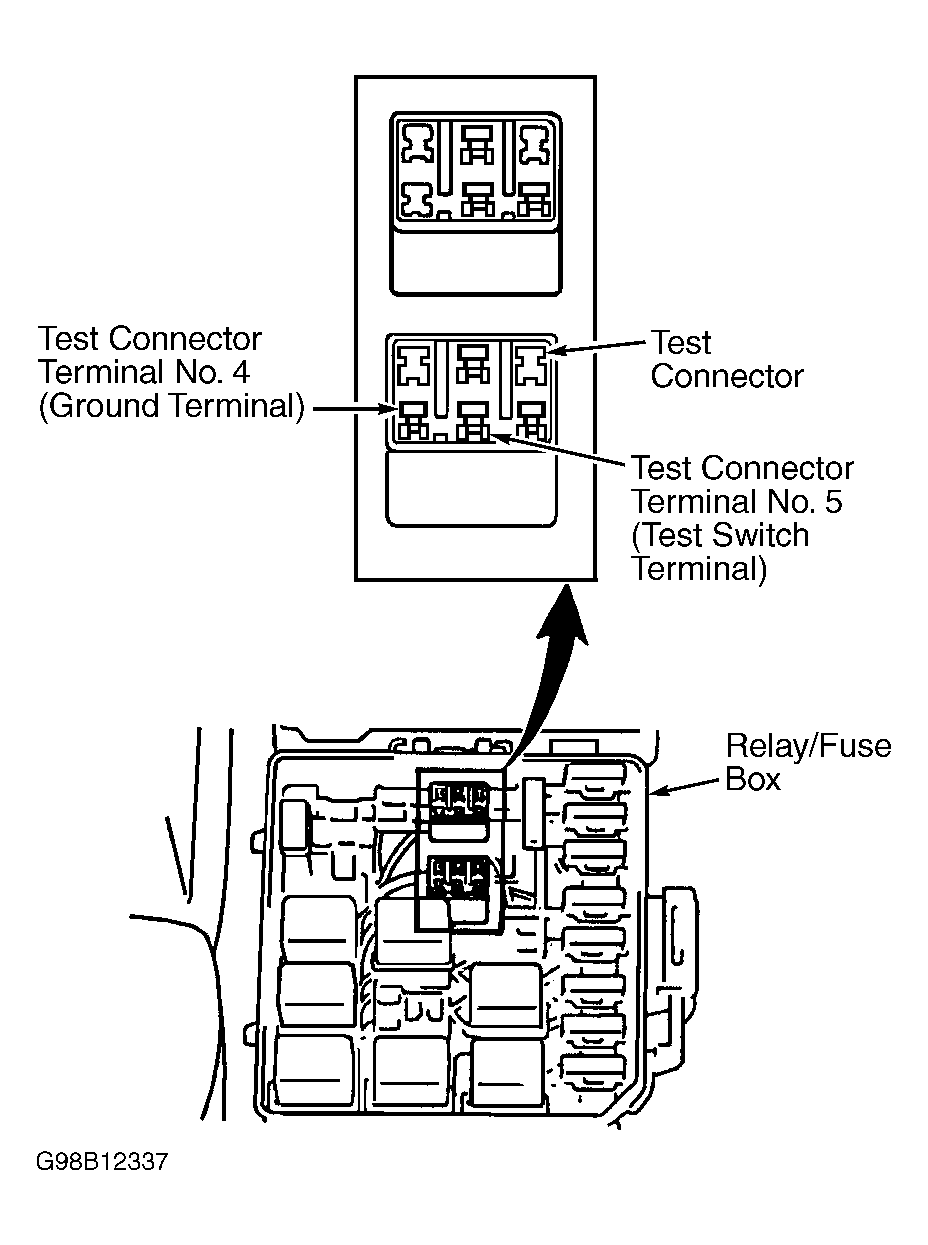
- Ensure test switch terminal of DIAG.-1 test connector (located in engine compartment fuse/relay block located in left side of engine compartment) is not grounded. See Fig 1
. If test switch terminal is grounded, remove jumper wire and repeat DTC CONFIRMATION TEST
. If test switch terminal is not grounded, go to next step.
- Turn ignition on. Measure voltage between ground and DIAG.-1 test connector terminal No. 5 (test switch terminal). If voltage is 10-14 volts, problem is probably intermittent. See INTERMITTENTS
in TROUBLE SHOOTING - NO CODES article. If reading is not 10-14 volts, go to next step.
- Check for short to ground in Purple/White wire between DIAG.-1 ignition timing adjustment test switch and ECM harness connector E92 terminal No. 7. See Figure
, and see WIRING DIAGRAMS
article. If problem is found, repair as necessary. After repair, repeat DTC CONFIRMATION TEST
. If no problem is found, go to next step.
- Substitute a known good ECM, and repeat DTC CONFIRMATION TEST
. If DTC does not reset, testing is complete.
 Courtesy of SUZUKI OF AMERICA CORP.