B1021
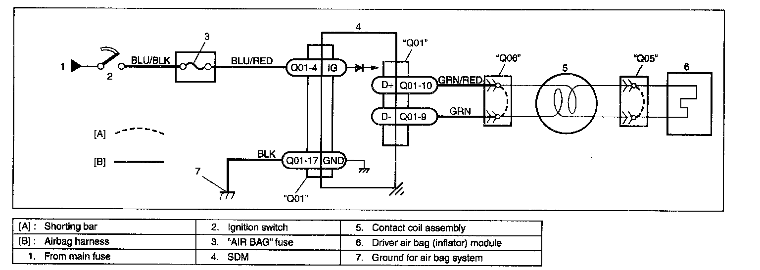
Wiring Diagram:
CAUTION:
- Be sure to perform AIR BAG DIAGNOSTIC SYSTEM CHECK before starting diagnosis according to flow table.
- When measurement of resistance or voltage is required in this table, use a tester along with a correct terminal adapter from special tool (Connector test adapter kit).
- When a check for proper connection is required, refer to INTERMITTENT AND POOR CONNECTIONS.
- If there is open circuit in the air bag wire harness, connector or terminal is found damaged, replace the wire harness, connector and terminal as an assembly.
DTC WILL SET WHEN
The combined resistance of the driver air bag (inflator) module, contact coil assembly, harness wiring and connector terminal contact is above a specified value for specified time.
TABLE TEST DESCRIPTION
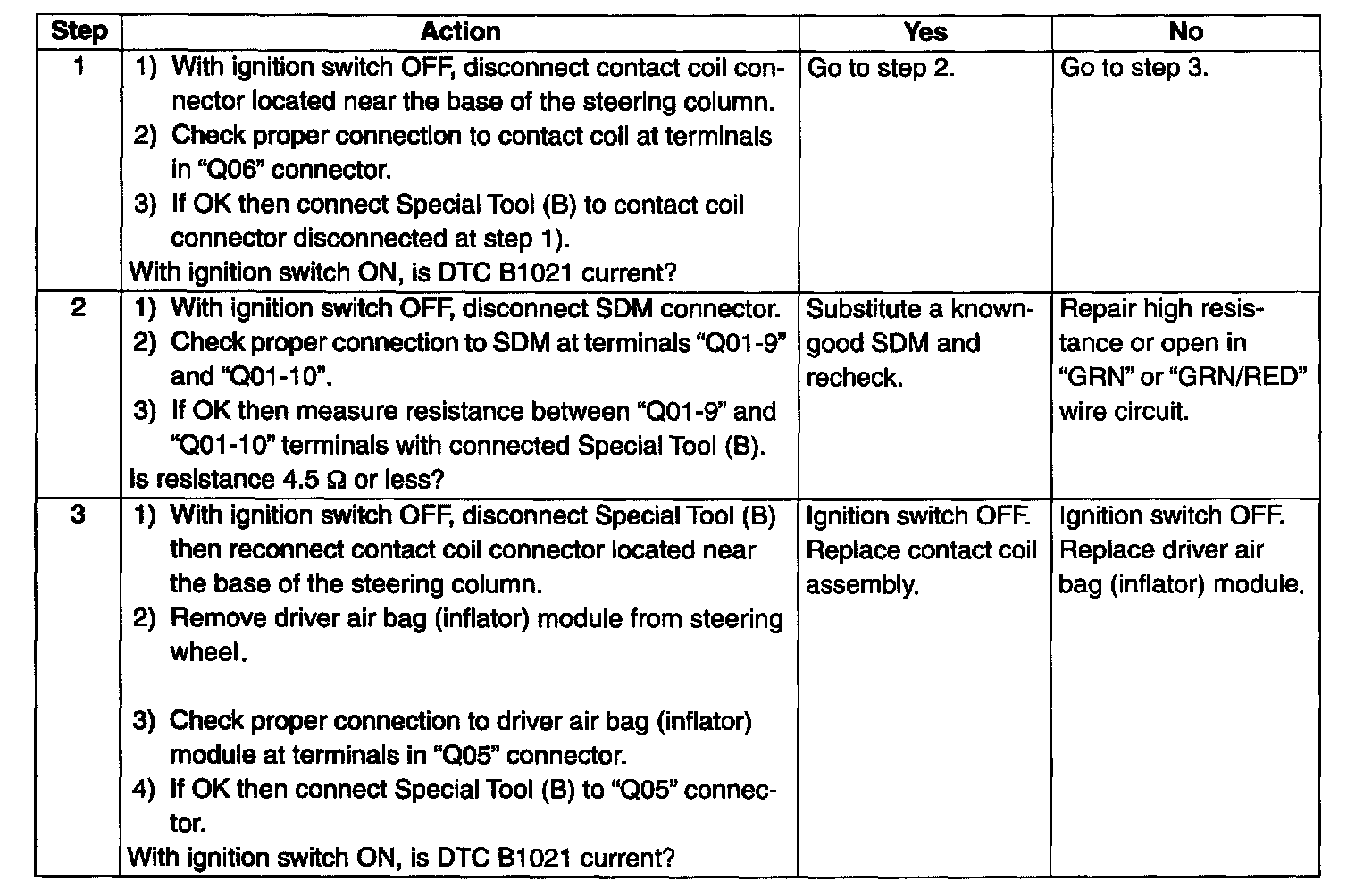
STEP 1: Check whether malfunction is in contact coil and driver air bag (inflator) module or the others.
STEP 2 : Check driver air bag (inflator) module initiator circuit in air bag harness.
STEP 3 : Check whether malfunction is in contact coil or driver air bag (inflator) module.
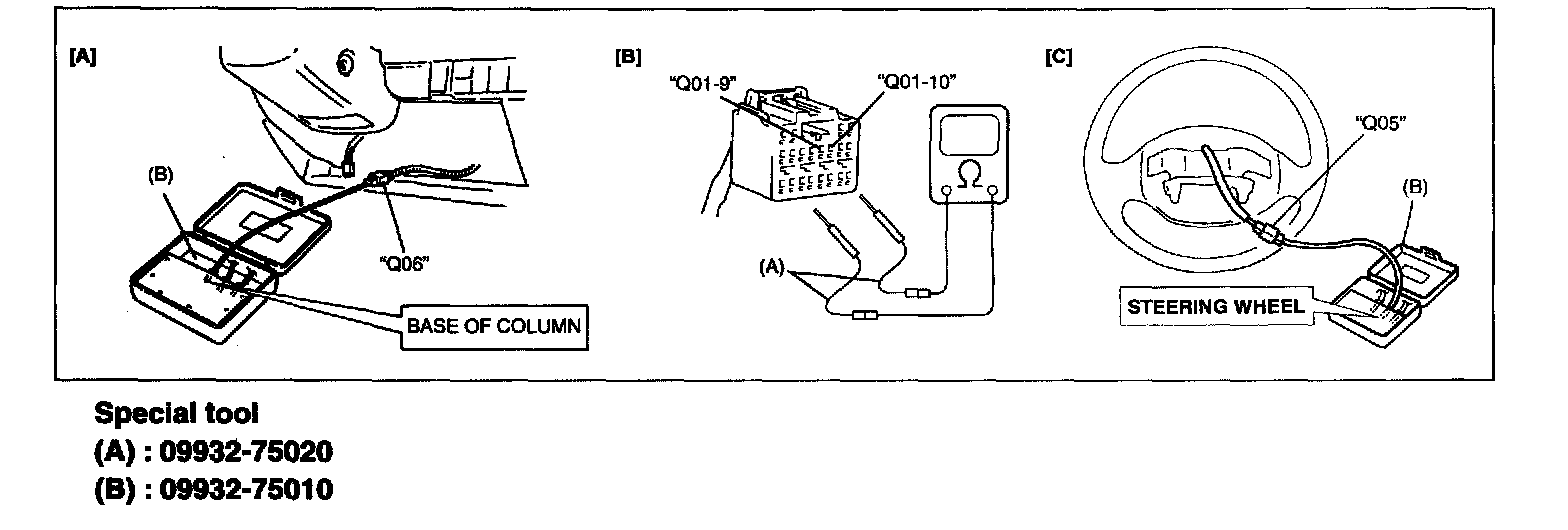
Step 1 - 3:
[A] Fig. For Step 1 And 2 / [B] Fig. For Step 2 / [C] Fig. For Step 3:
DIAGNOSTIC FLOW TABLE
NOTE: Upon completion of inspection and repair work, perform following items.
- Reconnect all air bag system components, ensure all components are properly mounted.
- Clear diagnostic trouble codes (Refer to DTC CLEARANCE), if any.
- Repeat AIR BAG DIAGNOSTIC SYSTEM CHECK to confirm that the trouble has been corrected.