Drive Bevel Pinion
DRIVE BEVEL PINION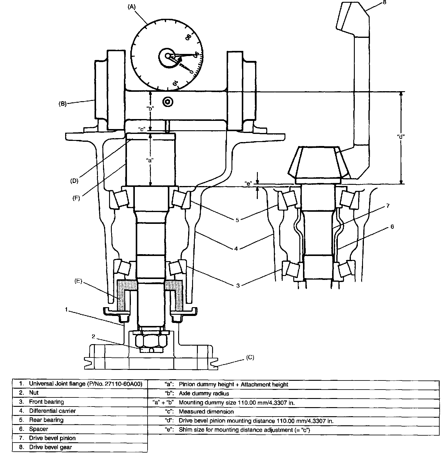
To engage drive bevel pinion and gear correctly, it is pre-required to install drive bevel pinion to differential carrier properly by using adjusting shim as described on the followings. Shown is relative positions of drive bevel pinion, differential carrier and mounting dummy.
Special tool
(A): 09900-20606
(B): 09926-78320
(C): 09922-75222
(D): 09922-76570
(E): 09951-46010
(F): 09926-78311-002
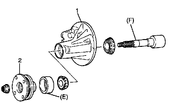
1. Install special tools with bearings and universal joint flange (2) to differential carrier (1).
NOTE: This installation requires no spacer or oil seal.
Special tool
(E): 09951-46010
(F): 09926-78311-002
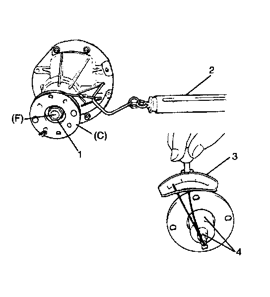
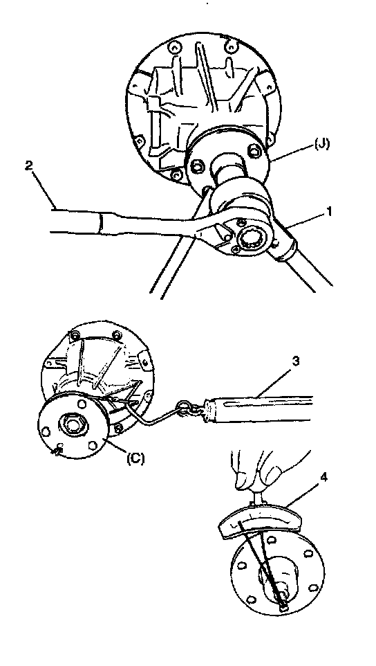
2. Tighten flange nut (1) so that specified bearing preload is obtained.
NOTE:
^ Before taking measurement with spring balance (2) or torque wrench (3), check for rotation by hand and apply small amount of differential oil to bearings.
^ On measuring preload, rotate the drive bevel pinion about 1 rotation per 2 seconds.
Special tool
(C): 09922-75222
(F): 09926-78311 -002
Pinion bearing preload :0.9 - 1.7 Nm (9.0 - 17.0 kg-cm, 7.8 - 14.7 inch lbs.)
Spring measure reading with special tool :18 N - 34N (1.8 - 3.4 kg, 4.0 - 7.5 lbs.)
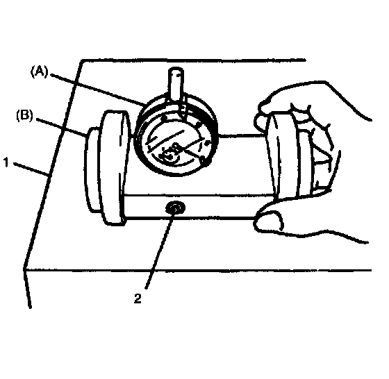
3. Set dial gauge to mounting dummy and make 0 (zero) adjustment on surface plate.
NOTE:
^ When setting dial gauge to mounting dummy, tighten screw lightly. Be careful not to over tighten it, which will cause damage to dial gauge.
^ With dial gauge set, turn dummy back and force by hand a couple of times and attain accurate 0 (zero) adjustment.
^ It is desirable that short pointer indicates beyond 2 mm when long one is at 0 (zero).
Special tool
(A): 09900-20606
(B): 09926-78320
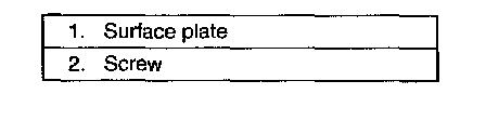
4. Place zero-adjusted mounting dummy and dial gauge set on pinion mounting dummy and take measurement between zero position and extended dial gauge measuring tip.
NOTE:
^ Repeat turning back and force of dummy and measure distance as far as top surface of pinion dummy accurately.
^ When dial gauge measuring tip extends from 0 (zero) position, pointer turns counterclockwise.
^ Measured value may exceed 1 mm. Therefore, it is also necessary to know reading of short pointer.
Special tool
(A): 09900-20606
(B): 09926-78311
(D): 09922-76570
(F): 09926-78311-002
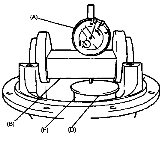
5. Obtain adjusting shim thickness by using measured value by dial gauge in previous step.
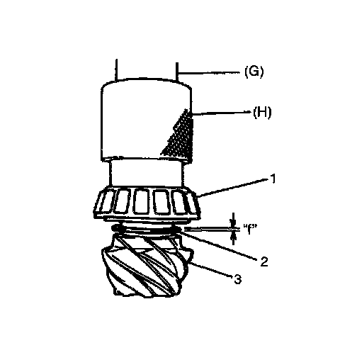
6. Select adjusting shim(s) (2) closest to calculated value from among following available sizes and put it in place and then press-fit rear bearing (1).
Calculated valve
"f": Closest value to "e" (refer to Step 5).)
Special tool
(G): 09925-18011
(H): 09927-66010
Available shim thickness
:1.12, 1.15, 1.18, 1.21, 1.24, 1.27, 1.30 and 0.3 mm
(0.044, 0.045, 0.046, 0.047 0.048, 0.049, 0.050 and 0.012 inch)
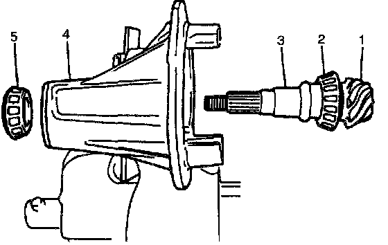
7. With new pinion spacer (3) inserted as shown in the figure, install front bearing (5) to differential carrier (4).
NOTE:
^ Make sure to use new spacer for reinstallation.
^ Apply differential oil to bearings.
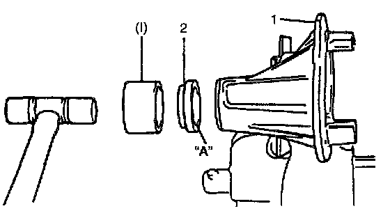
8. Using special tool and plastic hammer, drive oil seal (2)into differential carrier (1) till it becomes flush with carrier end. Then apply grease "A" to oil seal lip.
"A": Grease 99000-25010
Special tool
(1): 09951-18210
9. While tightening flange nut gradually with special tool and power wrench (4 - 10 magnification) (1), set preload of pinion to specification.
NOTE:
^ Before taking measurement with spring balance (3) or torque wrench (4), check for smooth rotation by hand.
^ On measuring preload, rotate the drive bevel pinion about 1 rotation per 2 seconds.
^ Be sure to tighten gradually and carefully till specified starting torque is obtained. Turning back overtightened flange nuts should be avoided.
Pinion bearing preload: 0.9 - 1.7 Nm (9.0 - 17.0 kg-cm, 7.8 - 14.7 inch lbs.)
Spring measure reading with special tool: 16 - 30 N (1.6 - 3.0 kg, 3.5 - 6.6 lbs.)
Special tool
(C): 09922-76560
(J): 09922-66021