Assembling Unit
ASSEMBLING UNIT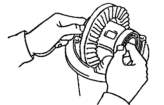
1. Place bearing outer races on their respective bearings. Used left and right outer races are not interchangeable.
2. Install case assembly in carrier.
3. Install side bearing adjusters on their respective carrier, making sure adjuster are threaded properly.
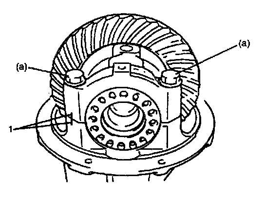
4. Align match marks (1) on cap and carrier. Screw in 2 side bearing cap bolts 2 or 3 turns and press down bearing cap by hand.
NOTE: If bearing cap does not fit tightly on carrier, side bearing adjuster is not threaded properly. Reinstall adjuster.
5. Tighten cap bolts (provisional torque).
Tightening torque
Bearing cap bolt (Provisional torque) (a): 15 Nm (1.5 kg-m, 11.0 ft. lbs.)
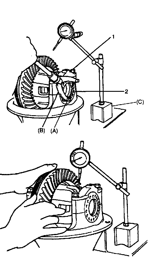
6. Tighten both bearing adjusters (2) so as to obtain specified gear backlash and at the same time, obtain preload of side bearing.
NOTE:
^ Be sure to apply measuring tip of dial gauge at right angles to convex side of tooth.
^ As a practical measure the following would be recommended to obtain specified backlash and side bearing preload at the same time.
^ Obtain specified backlash by turning both adjusters inward lightly.
^ Tighten both adjusters further by one notch at a time.
^ Measure at least 4 points on drive bevel gear periphery.
Standard backlash: 0.13 - 0.18 mm (0.005 - 0.007 inch)
Special tool
(A): 09930-40120
(B): 09930-40113
(C): 09900-20701
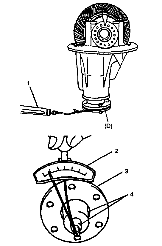
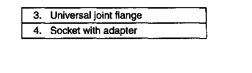
7. Measure preload of pinion bearing with spring balance (1) or torque wrench (2)and check composite preload of pinion bearing and side bearing.
NOTE:
^ Before taking measurement with spring balance (1) or torque wrench (2), check for smooth rotation by hand.
^ On measuring preload, rotate the drive bevel pinion about 1 rotation per 2 seconds.
Composite preload of pinion bearing and side bearing: 1.1 - 2.0 Nm (11.0 - 20.0 kg-cm, 9.5 - 17.4 inch lbs.)
Spring measure reading with special tool: 19.5 - 35.5 N (1.95 - 3.55 kg, 4.30 - 7.83 lbs.)
Special tool
(D): 09922-76560
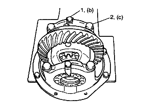
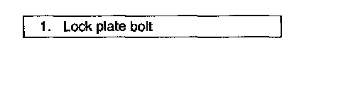
8. Torque bearing cap bolts (2) to specification and install bearing lock plates.
Tightening torque
Lock plate bolt (b): 12 Nm (1.2 kg-m, 9.0 ft. lbs.)
Bearing cap bolt (c): 85 Nm (8.5 kg-m, 61.5 ft. lbs.)
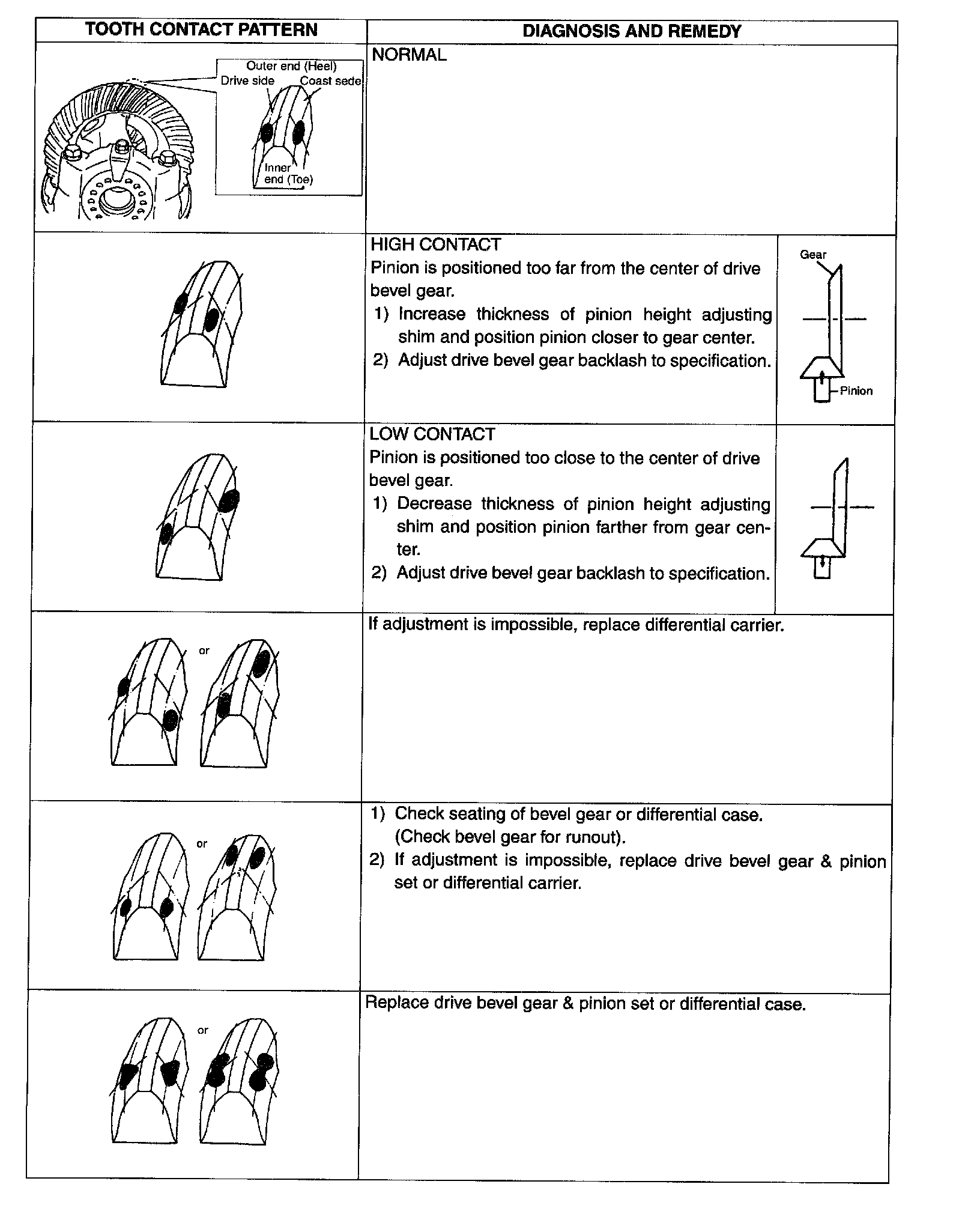
9. As final step, check gear tooth contact as follows.
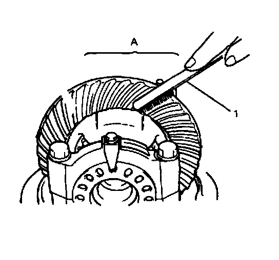
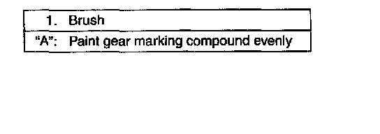
a. After cleaning 10 drive bevel gear teeth, paint them with gear marking compound evenly by using brush or sponge etc.
b. Turn gear to bring its painted part in mesh with drive bevel pinion and turn it back and forth by hand to repeat their contact.
c. Bring painted part up and check contact pattern, referring to following chart. If contact pattern is not normal, readjust or replace as necessary according to instruction in chart.
NOTE: Be careful not to turn drive bevel gear more than one full revolution, for it will hinder accurate check.
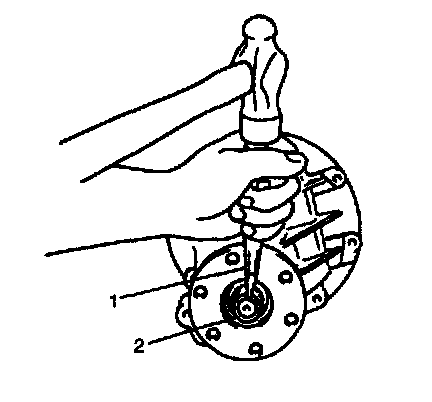
10. Upon completion of gear tooth contact check in Step 9., caulk flange nut (2) with caulking tool (1) and hammer.