P0440
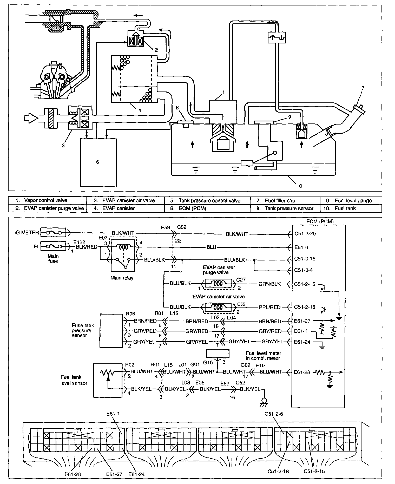
SYSTEM/WIRING DIAGRAM
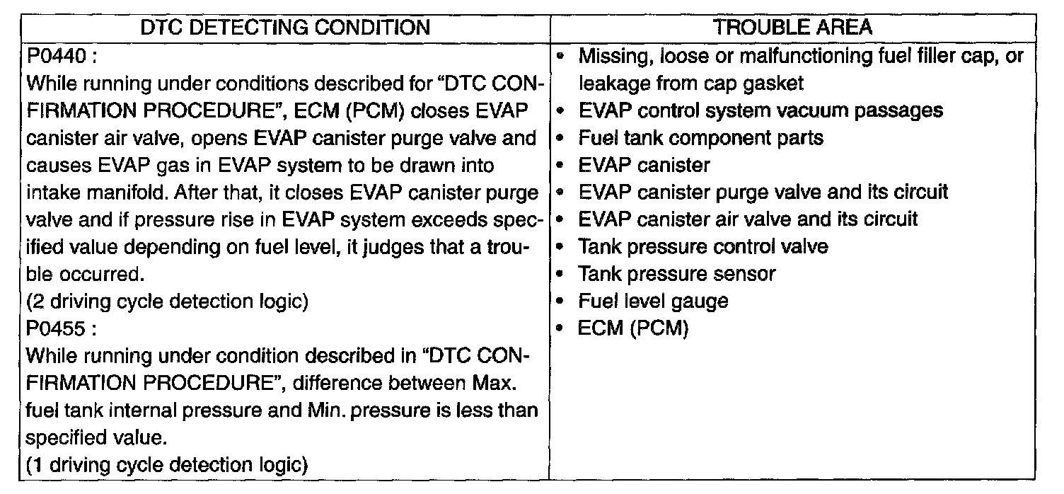
Detecting Condition And Trouble Area:
DTC CONFIRMATION PROCEDURE
WARNING:
- When performing a road test, select a place where there is no traffic or possibility of a traffic accident and be very careful during testing to avoid occurrence of an accident.
- Road test should be carried out with 2 persons, a driver and a tester, on a level road.
NOTE:
Check to make sure that following conditions are satisfied when using this "DTC CONFIRMATION PROCEDURE".
- Intake air temp.: -8 °C (18 °F) or higher
- Engine coolant temp.: -8 - 110 °C (18 - 230 °F)
- Altitude (barometric pressure) : 2400 m, 8000 ft or less (560 mmHg (75 kPa) or more)
- Indication of fuel level meter in combination meter : Lower than 3/4
1. Connect scan tool with ignition switch OFF.
2. Turn ON ignition switch and clear DTC, pending DTC and freeze frame data by using scan tool and start engine.
3. Increase vehicle speed to 55 km/h (35 mph) or more.
4. keep driving above vehicle speed for about 20 min. (Change of vehicle speed is permitted in this step).
5. Keep driving 50 - 60 km/h (30 - 40 mph) for about 3 min (Throttle valve opening is kept constant in this step).
6. Stop vehicle and check if DTC and pending DTC exists by using scan tool. If not, check if evaporative system monitoring test has completed by using scan tool. If not in both of above checks (i.e., no pending DTC and evaporative system monitoring test not completed), check vehicle conditions (environmental) and repeat Step 3) through 6).
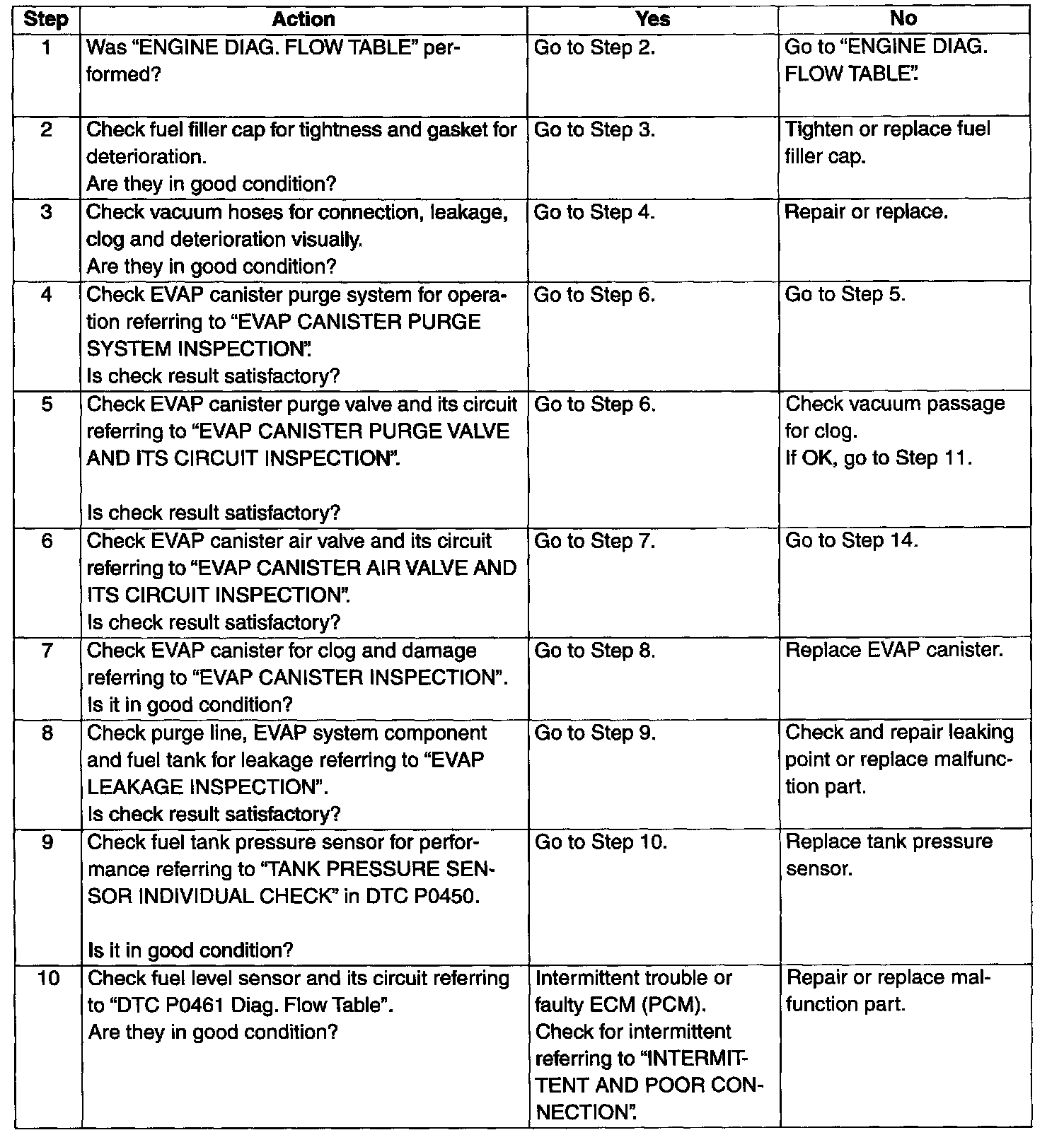
Steps 1 - 10:
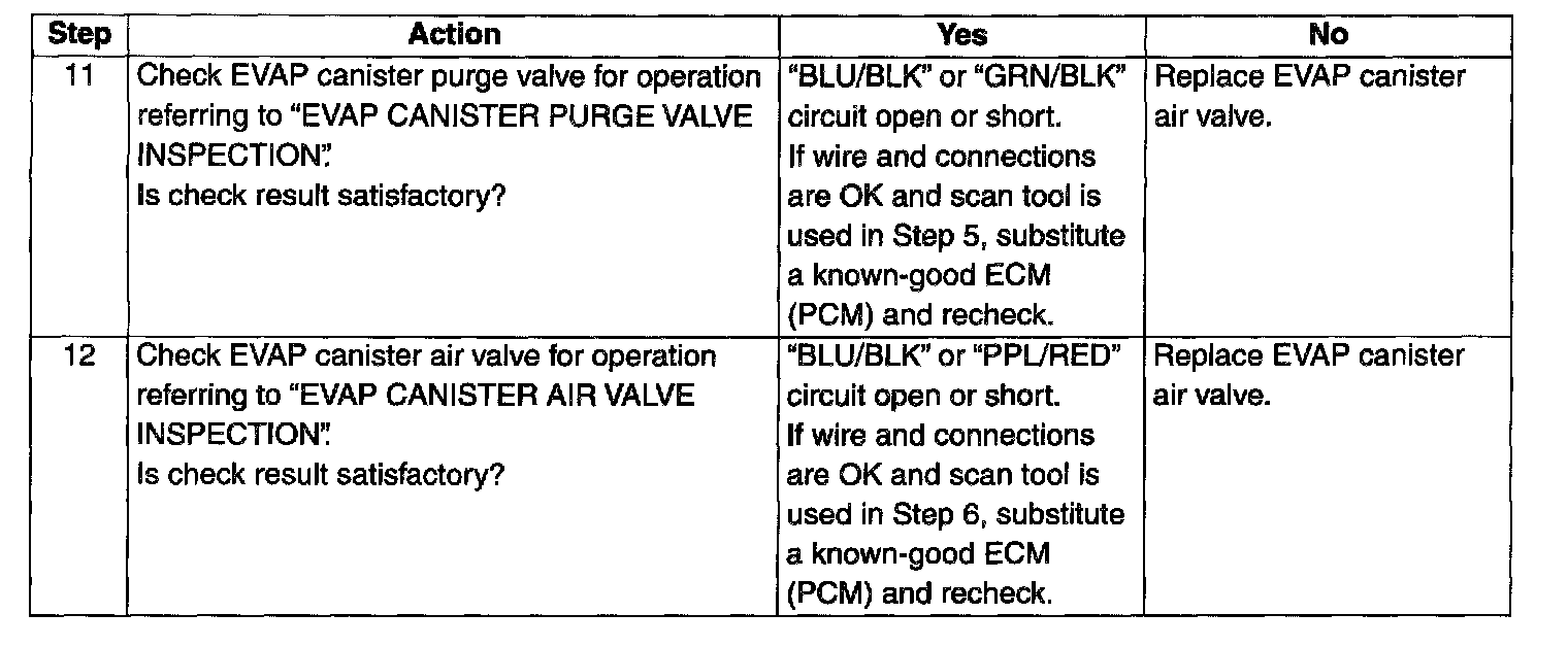
Steps 11 - 12:
TROUBLESHOOTING
WARNING: This work must be performed in a well ventilated area and away from any open flames such as gas hot water.
EVAP CANISTER PURGE SYSTEM INSPECTION
1. Warm up engine to normal operating temperature.
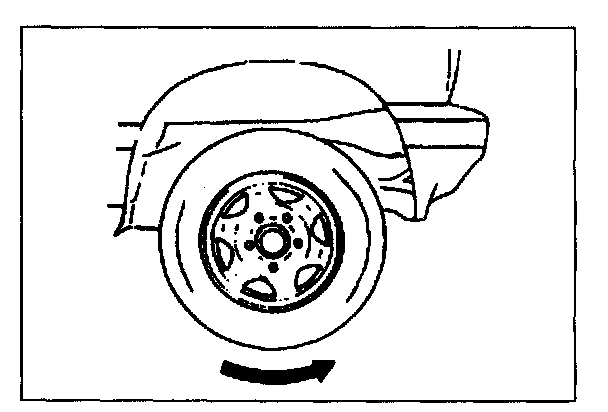
2. Hoist vehicle so that all wheels rotate freely.
3. Set M/T in "Neutral" or A/T in "P" position and parking brake.
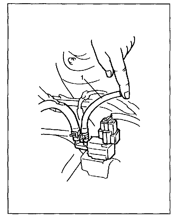
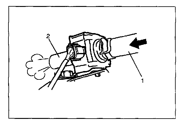
4. Disconnect purge hose (1) from EVAP canister.
5. Place finger against the end of disconnected hose (1) and check that vacuum is not felt there when engine is running at idle speed.
6. Release parking brake lever, set transfer in "2H" and M/T in "1st" or A/T in "L"
WARNING: Make sure that transfer is set to "2H" range position for this check. If it is set to "4H" or "4L" position, front and rear wheels turn at high speed and a very dangerous situation may occur.
7. Also check that vacuum is felt when engine speed is increased to higher than about 1,500 r/min. and keep it for 3 min. or more. If check result is not described in steps 5) and 7), check EVAP canister purge valve, wire harness and vacuum passage.
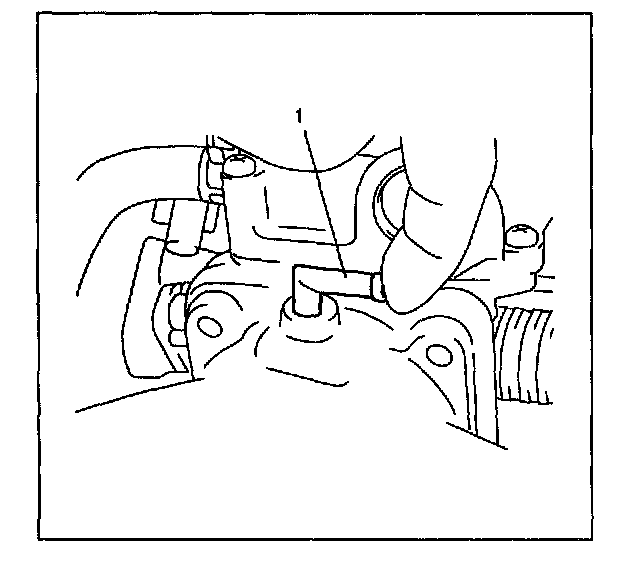
VACUUM PASSAGE INSPECTION
Start engine and run it at idle speed. With finger placed against vacuum nozzle (1), check that vacuum is applied.
If it is not applied, clean vacuum passage by blowing compressed air.
VACUUM HOSE INSPECTION
Check hoses for connection, leakage, clog and deterioration. Replace as necessary.
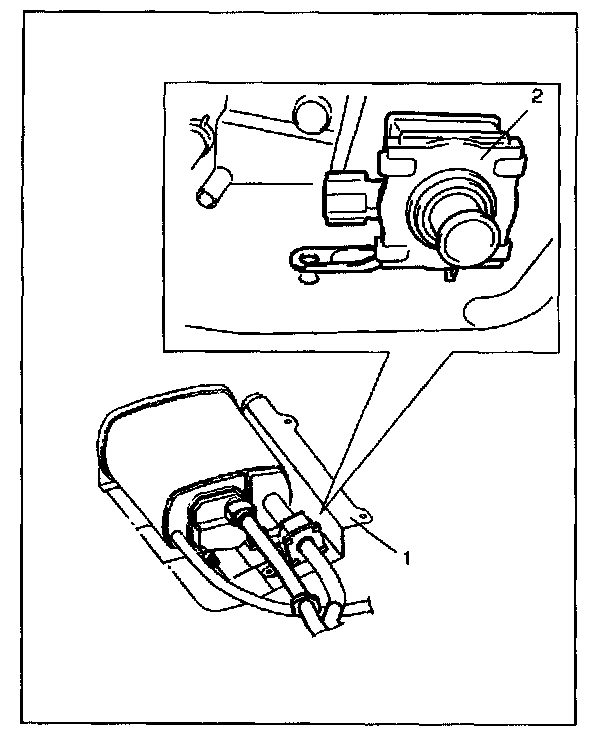
EVAP CANISTER PURGE VALVE AND ITS CIRCUIT INSPECTION
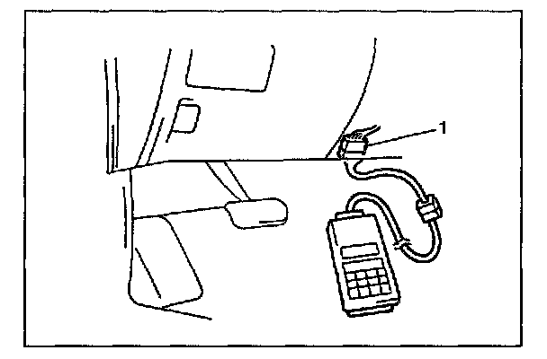
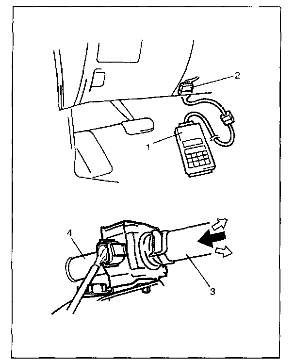
1. Connect SUZUKI scan tool to DLC (1) with ignition switch OFF and disconnect vacuum hoses from each pipe.
2. Turn ignition switch ON, clear DTC and select "MISC TEST" mode on SUZUKI scan tool.
3. Check purge valve for operation and vacuum passage for clog when valve is switched ON and OFF by using SUZUKI scan tool.
If check result is not described, check vacuum hoses, purge valve, wire harness and connections.
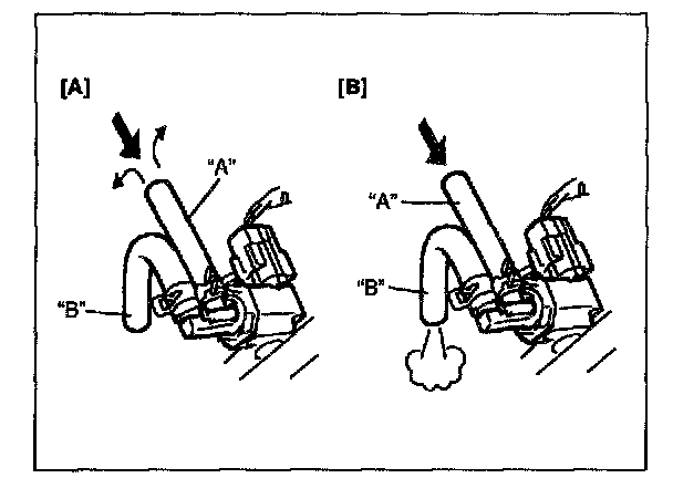
EVAP canister purge valve:
Valve OFF [A]: When blowing into hose "A", air should not come out of hose "B".
Valve ON [B] : When blowing into hose "A", air should come out of hose "B".
EVAP CANISTER PURGE VALVE INSPECTION
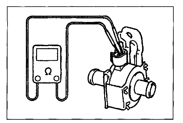
1. With ignition switch OFF, disconnect coupler from canister purge valve.
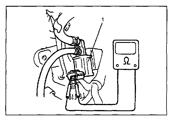
2. Check resistance between two terminals of EVAP canister purge valve (1).
If resistance is as specified, proceed to next operation check. If not, replace.
Resistance of EVAP canister purge valve: 28 - 35 ohm at 20 °C (68 °F)
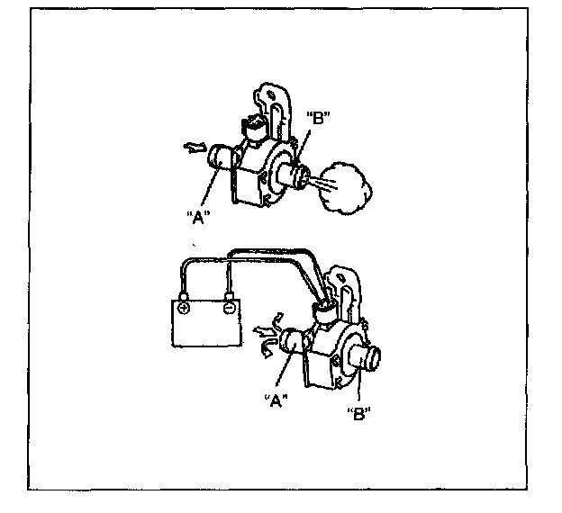
3. Disconnect vacuum hoses from intake manifold and its EVAP canister.
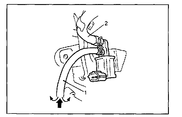
4. With coupler disconnected, blow into hose "A" (1). Air should not come out of hose "B" (2).
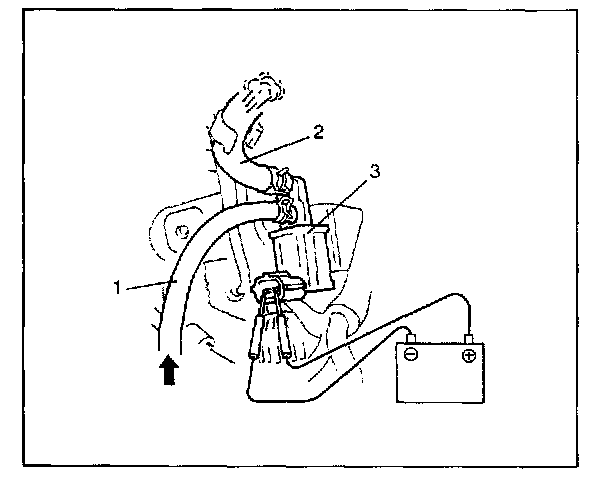
5. Connect 12 V-battery to EVAP canister purge valve (3) terminals. In this state, blow hose "A" (1).
Air should come out of hose "B" (2).
If check result is not as described, replace EVAP canister purge valve.
WARNING: Do not suck the air through valve. Fuel vapor inside valve is harmful.
6. Connect vacuum hoses.
7. Connect EVAP canister purge valve coupler securely.
EVAP CANISTER AIR VALVE AND ITS CIRCUIT INSPECTION
WARNING: Do not suck the air through valve. Fuel vapor inside valve is harmful.
1. Disconnect hose from EVAP canister.
2. With ignition switch ON, blow into hose "A" (1). Air should come out of hose "B" (2).
3. Connect SUZUKI scan tool (1) to DLC (2) with ignition switch OFF
4. Turn ON EVAP canister air valve by using SUZUKI scan tool with ignition switch ON.
In this state, blow from "A" (3). Air should not come out of "B" (4).
If check results are as describe above, EVAP canister air valve and its circuit are in good condition, connect vacuum hoses securely.
If not, check air valve, wire harness and connections.
EVAP CANISTER AIR VALVE INSPECTION
1. With ignition switch OFF, disconnect coupler from EVAP canister air valve.
2. Remove canister bracket from vehicle body.
3. Check resistance between two terminals of EVAP canister air valve.
If resistance is as specified, proceed to next step. If not, replace.
Resistance of EVAP canister air valve:
25 - 30 ohm at 20 °C (68 °F)
4. Disconnect vacuum hoses from EVAP canister.
5. With coupler disconnected, blow from "A". Air should come out of "B".
If not, replace EVAP canister air valve.
6. Connect 12 V-battery to EVAP canister air valve terminals. In this state, blow from "A".
Air should not come out of "B".
If check result is not specified above, replace EVAP canister air valve.
WARNING: Do not suck the air through valve. Fuel vapor inside valve is harmful.
7. Install EVAP canister air valve (2) to canister bracket (1) and canister bracket to vehicle body.
8. Connect vacuum hose.
9. Connect EVAP canister air valve coupler securely.
TANK PRESSURE CONTROL VALVE INSPECTION
WARNING: DO NOT SUCK air through tank pressure control valve. Fuel vapor inside the valve is harmful.
1. Disconnect hoses and remove tank pressure control valve.
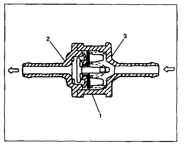
2. Air should pass through valve smoothly from black side (3) of tank pressure control valve (1) to orange side (2) when blown hard.
3. From orange side, even when blown softly, air should come out of black side.
4. If air doesn't pass through valve in Step 2) or hard blow is required in Step 3), replace tank pressure control valve.
5. Plug orange nozzle and apply 26 kPa (20 cmHg) vacuum to black nozzle. Check that vacuum is held at that level (there is no leakage).
If vacuum leaks, replace.
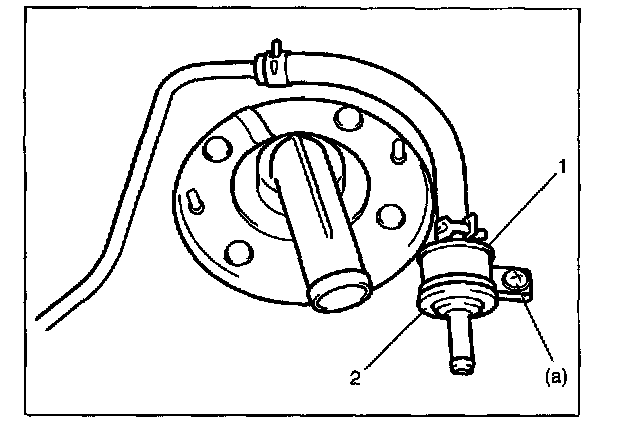
6. Install tank pressure control valve to fuel tank in such direction that vapor flows from its black nozzle side (1) to wards canister side (2).
Tightening torque
Tank pressure control valve mounting screw (a):
1.6 N.m (0.16 kg-m, 1.02 lb-ft)
7. Connect hoses to tank pressure control valve and clamp them securely.
EVAP CANISTER INSPECTION
WARNING: DO NOT SUCK nozzles on EVAP canister. Fuel vapor inside EVAP canister is harmful.
1. Disconnect vacuum hoses from EVAP canister.
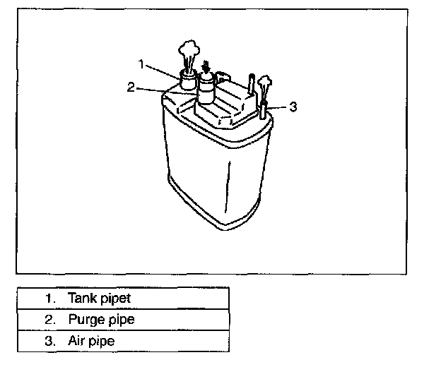
2. When air is blown into tank pipe, there should be no restriction of flow through purge pipe and air pipe.
3. If operation differs from above description, EVAP canister must be replaced.
4. Connect hoses to canister.
EVAP LEAKAGE INSPECTION
1. Disconnect purge hose from intake manifold and tank pressure control valve hose (if equipped) from solenoid vacuum valve.
2. Turn EVAP canister purge valve ON (open) using SUZUKI scan tool.
3. Plug air valve hose end.
4. Apply 3.5 kPa (14.0 in Aq, 26.0 mmHg) to purge hose and seal it. After 15 second, check to make sure that pressure is higher than 3.3 kPa (13.6 in Aq, 24.5 mmHg).
If check result is not satisfactory, locate pressure leaking point by using soap water or leak detector.
If no pressure leakage exists in vapor purge line, fuel filler cap, filler neck and etc., remove fuel tank from vehicle and check for leakage from installation face of parts installed on fuel tank and hose joint.