Door Knob Switch & Hazard Warning Light Circuit
- Disconnect negative battery cable. Disconnect Power Door Lock and Remote Keyless Entry (PDL/RKE) controller harness connector. Connect negative battery cable.
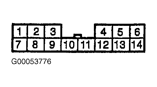
- Using DVOM connected to chassis ground, check for voltage at PDL/RKE controller connector terminal No. 6 (Brown wire). See Fig 1
. If reading indicates 10-14 volts, go to next step. If 10-14 volts do not exist, check for an open or shorted condition in Brown wire between PDL/RKE connector to keyless entry relay No. 1 and keyless entry relay No. 2. See Figure
or Figure
. See WIRING DIAGRAMS
.
- Connect DVOM between ground and PDL/RKE controller connector terminal No. 11 (Green wire). See Fig 1
. Ensure continuity exists with driver door lock knob pulled up, and continuity does not exist when driver door lock knob is pushed down. If readings are as described, circuit is okay. If readings are not as described, check driver's door key switch. See DOOR LOCK KEY CYLINDER SWITCH TEST
in COMPONENT TESTS. If driver's door key switch is okay, repair open or shorted condition in Green wire. See WIRING DIAGRAMS
.
 Courtesy of SUZUKI OF AMERICA CORP.