ABS Actuator Assembly
ABS ACTUATOR ASSEMBLY (HYDRAULIC MODULATOR/MOTOR PACK ASSEMBLY)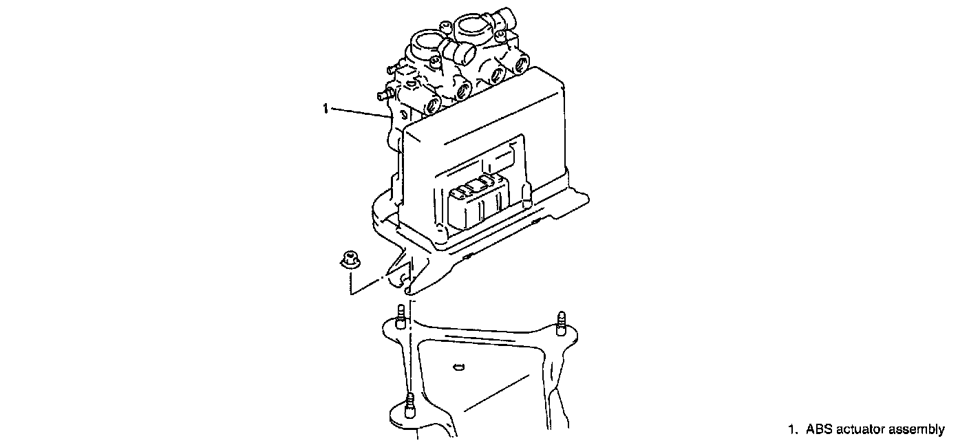
REMOVAL
WARNING: To help avoid personal injury, due to a retained load on the hydraulic modulator/motor pack assembly, the gear tension relief function of the TECH-1 must be performed prior to removal of the hydraulic modulator.
1. Using the TECH-1, perform the gear tension relief sequence.
2. Remove battery from vehicle.
3. Drain brake fluid in reservoir, master cylinder and ABS actuator assembly.
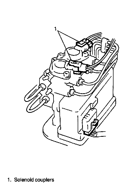
4. Disconnect solenoid couplers.
NOTE: Place a shop towel beneath the hydraulic modulator brake pipes to prevent brake fluid from contaminating motor pack or electrical couplers.
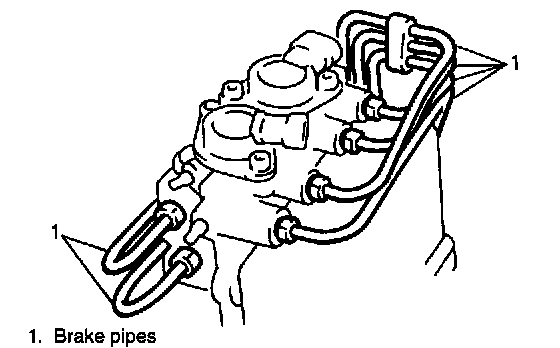
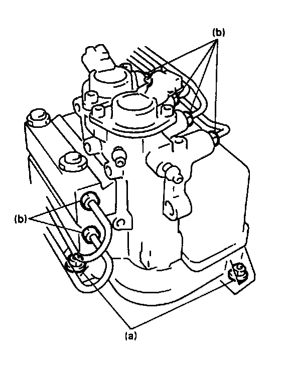
5. Disconnect brake pipes from ABS actuator with special tool.
Special Tool (Flare nut wrench)
(A): 09950-78210
NOTE: Do not allow brake fluid to get on painted surface, motor and electrical couplers.
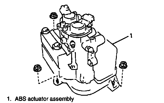
6. Remove ABS actuator assembly from vehicle.
7. Disconnect motor pack harness coupler.
INSTALLATION
Install ABS actuator assembly in reverse order of REMOVAL procedure, noting the following points.
^ Torque all fasteners to specifications.
Tightening Torque
(a): 10 Nm (11.0 kg.m, 7.5 ft. lbs.)
(b): 16 Nm (11.6 kg.m, 11.5 ft. lbs.)
^ After installing, bleed air from brake system.