Symptom Related Diagnostic Procedures
DIAGNOSIS TABLE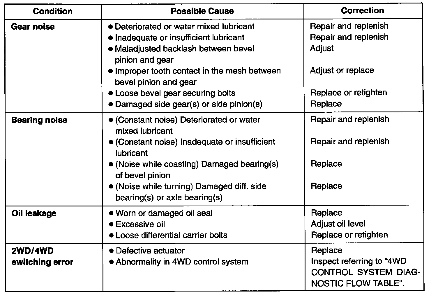
Differential Assembly
4WD Control System Diagnostic Flow Table
Before performing the trouble diagnosis, check that the transfer and front differential are in good condition and there is no air leakage from air hoses and the actuator.
[NOTES ON SYSTEM CIRCUIT INSPECTION]
- For system circuit, refer to the figure under Differential; Description and Operation; Front Differential; 4WD Control System.
For G16/J20 engine model
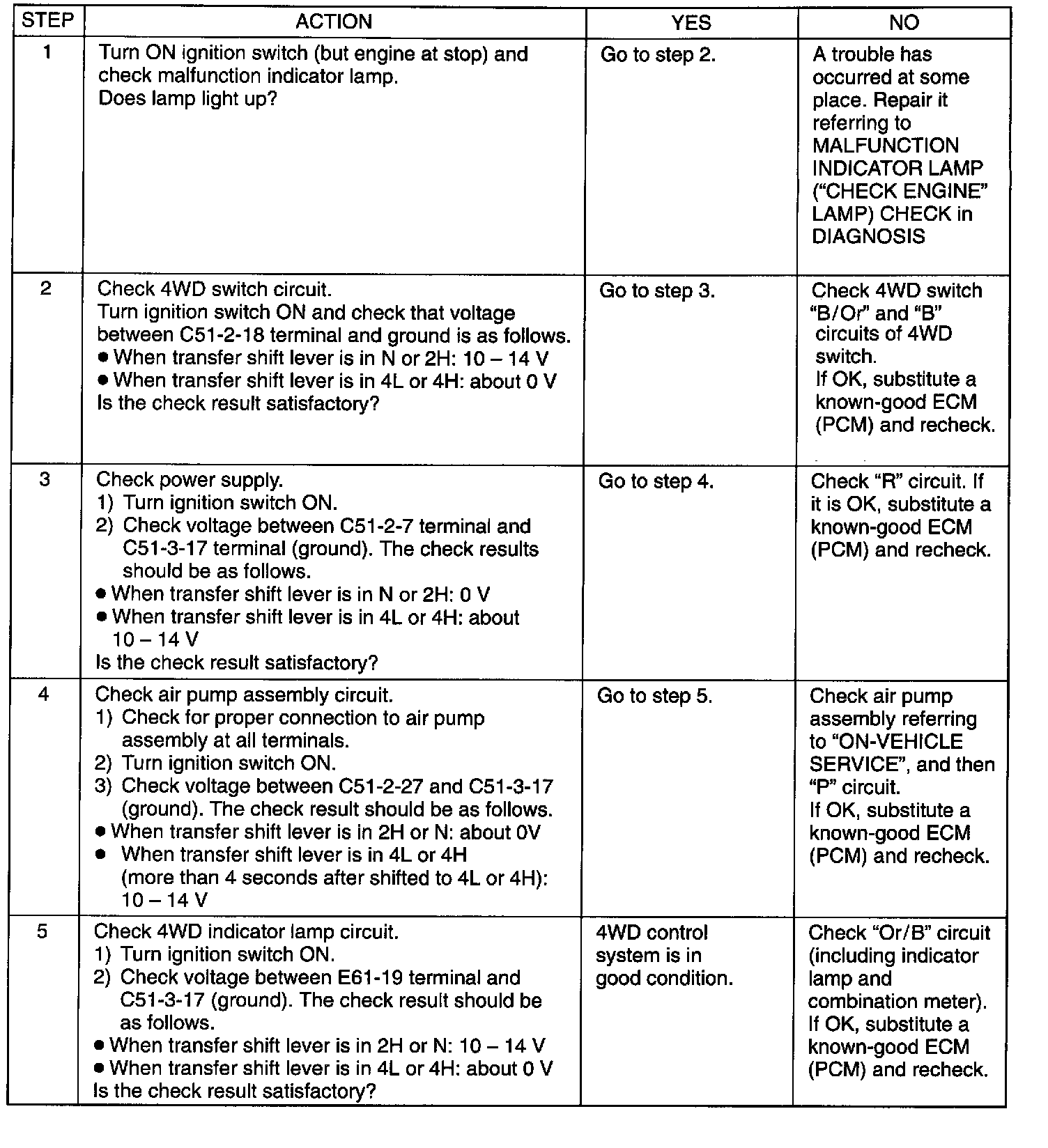
Step 1 - 5
For H25 engine model
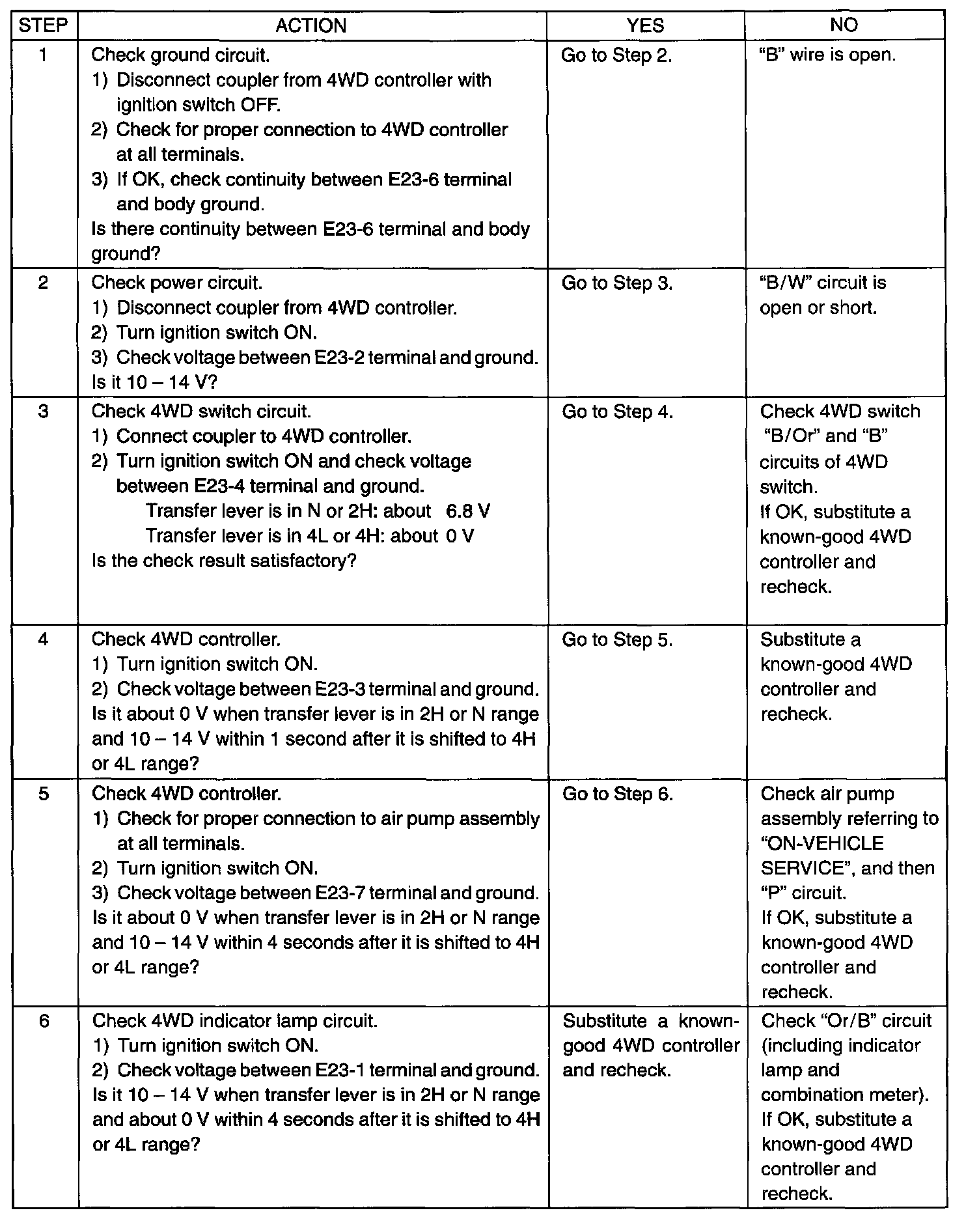
Step 1 - 6
4WD CONTROL CIRCUIT INSPECTION
Voltage Check [G16 and J20 engine models]
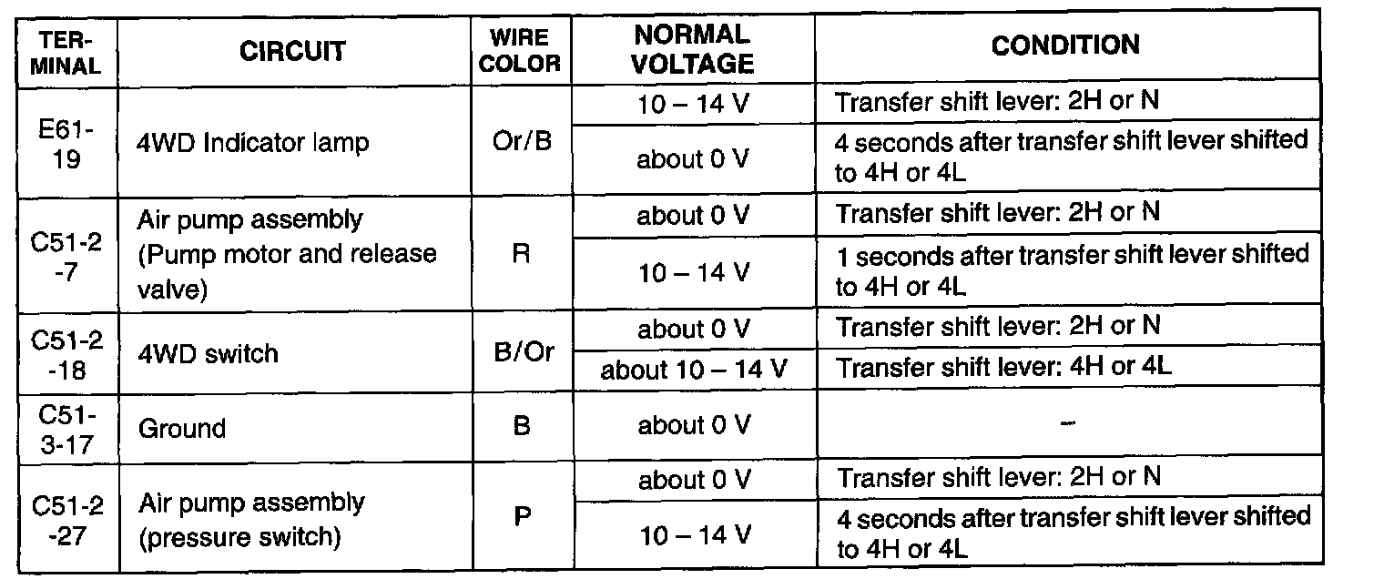
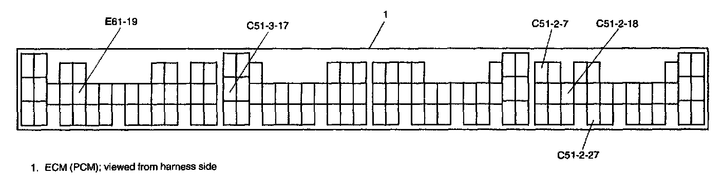
Check for input or output voltage (voltage between each circuit and body ground) of ECM Powertrain Control Module (PCM) with ECM (PCM) connector connected and ignition switch turned ON.
Voltage Check [H25 engine model]
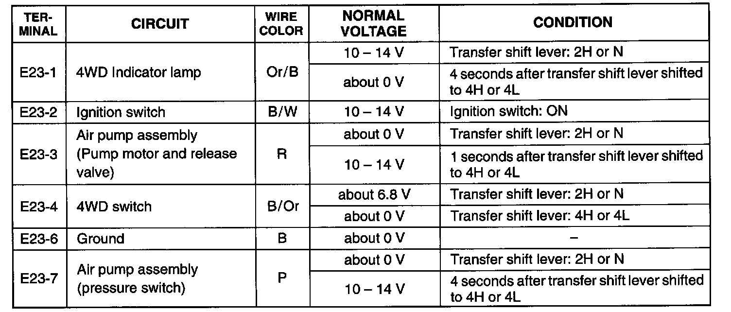
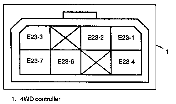
Check for input or output voltage of 4WD controller (voltage between each circuit and body ground) with 4WD controller connector connected and ignition switch turned ON.