Axle Service
DISASSEMBLY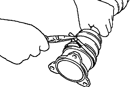
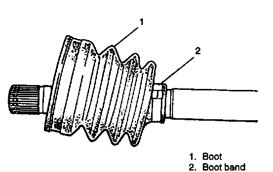
1. Remove boot band of differential side joint.
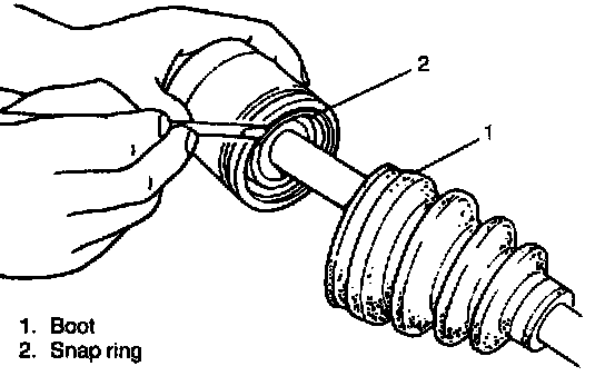
2. Slide boot toward the center of shaft and remove snap ring from outer race, then take shaft out of outer race.
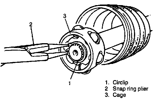
3. Remove circlip and then cage.
4. Remove inside and outside boots from shaft.
CAUTION:
- Do not disassemble wheel side joint (outboard joint). If any malcondition is found in joint, replace it as assembly.
- Do not disassemble ball joint of differential side joint. If any malcondition is found in ball joint, replace differential side joint assembly.
INSPECTION
- Check boots for breakage or deterioration. Replace them as necessary.
- Check circlip, snap ring and boot bands for breakage or deformation. Replace as necessary.
CLEANING
- Wash disassembled parts (except boots) in degreaser. After washing, dry parts completely by blowing air.
- Clean boots with cloth. DO NOT wash boots in degreaser, such as gasoline or kerosene, etc..
Washing in degreaser causes deterioration of boot.
ASSEMBLY
CAUTION:
- To prevent any problem caused by washing solution, do not wash joint boots. Degreasing of those parts with cloth is allowed.
- For M/T vehicle with H25 engine
- To ensure full performance of joint as designed, be sure to distinguish between two types of grease in repair set and apply specified volume to respective joint. i.e. yellow grease to wheel side joint and black one to differential side.
- Bend each boot band against forward rotation.
- Do not squeeze or distort boot when fastening it with bands.
Distorted boot caused by squeezing air may reduce its durability.
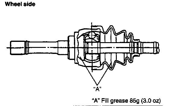
1. Fully apply joint grease to wheel side joint. Use joint grease in the tube included in spare part.
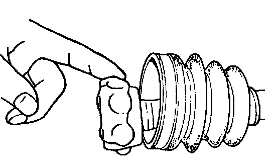
2. Fit wheel side boot on shaft. Fill up inside of boot with joint grease of about 90 gram. Before fixing boot band, insert screwdriver into boot on joint side and allow air to enter boot so that air pressure in boot becomes the same as atmospheric pressure.
3. Fixing boot band.
4. Install boot onto drive shaft till its small diameter side fits to shaft groove and fix there with boot band.
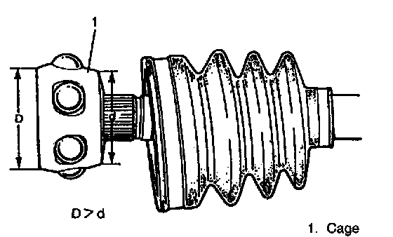
5. Install cage to shaft.
CAUTION: Install cage directing smaller outside diameter side to shaft end.
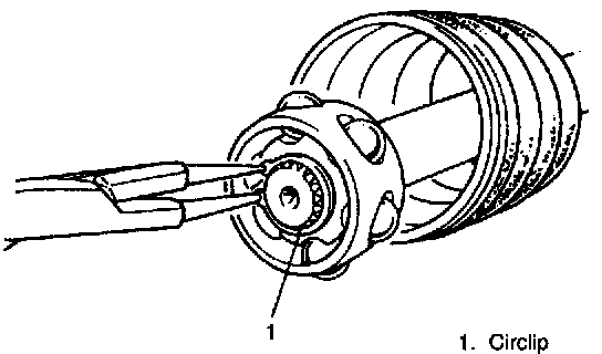
6. Install circlip by using snap ring plier.
7. Apply grease to entire surface of cage. Use joint grease in tube included in spare part or joint grease (99000-25120).
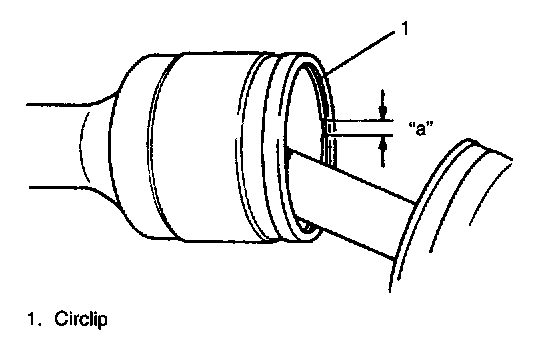
8. Insert cage into outer race and fit circlip into groove of outer race.
CAUTION: Position opening of circlip "a" so that it will not be lined up with a ball.
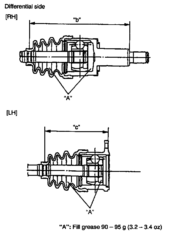
9. Apply grease to inside of outer race, and fit boot to outer race. Fill up inside of boot with joint grease.
"A": Joint Grease 99000-25120 (about 90 - 95g /3.2 - 3.4 oz.)
10. Fitting boot to outer race, adjust so that measurements "b" and "c" become as indicated in figure.
Length "b": 203.2 - 213.2 mm
(8.00 - 8.40 inch)
196.8 - 206.8 mm
(7.75 - 8.14 inch) M/T vehicle with H25 engine
"c": 125.5 - 135.5 mm
(4.94 - 5.33 inch)
127.5 - 137.5 mm
(5.02 - 5.41 inch) M/T vehicle with H25 engine
Before fixing boot band, insert screwdriver into boot on joint side and allow air to enter boot so that air pressure in boot becomes the same as atmospheric pressure.
11. Clamp boot band. Check boots for distortion or dent.
INSTALLATION
Install drive shaft assembly by reversing removal procedure and noting following points.
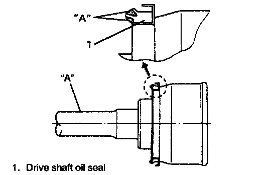
- Clean front drive shaft oil seal and then apply lithium grease to oil seal and DOJ shaft.
"A": Grease 99000-25010
- Check oil seal for breakage or deterioration. Replace it as necessary.
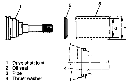
- Drive in oil seal until its end contacts stepped surface of drive shaft joint by using a pipe whose inner diameter is 76 mm (2.992 inch) or more and outer diameter is 80 mm (3.150 inch) or less.
Diameter "a": 76 mm (2.992 inch) or more
Diameter "b": 80 mm (3.150 inch) or less
- Drive in drive shaft thrust washer (Vehicle with G16 or J20 engine).
- RH Side
Push differential side joint by hand until it is positioned by snap ring fitted to its spline.
LH Side
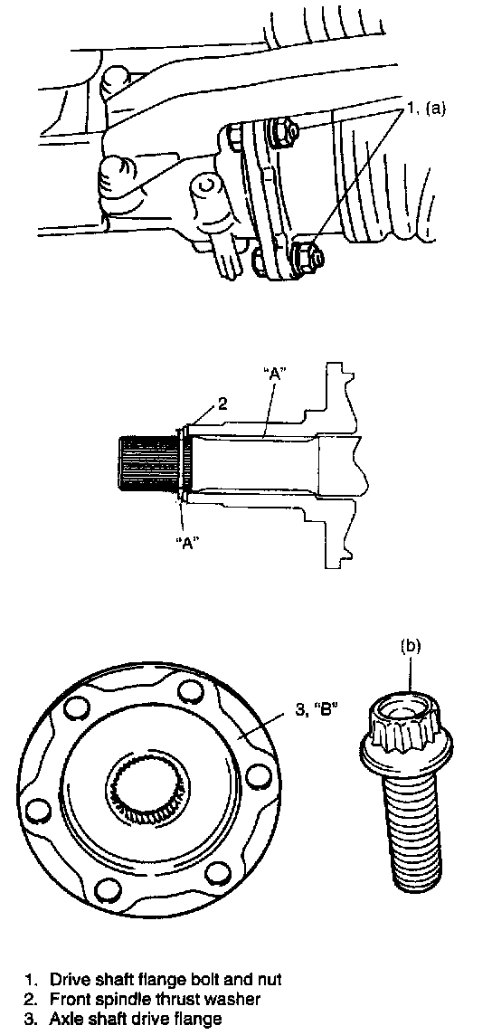
Connect drive shaft flange bolts and nuts.
Tightening Torque
(a): 50 Nm (5.0 kg.m, 36.5 ft. lbs.)
- Apply grease to front spindle thrust washer and front spindle part of drive shaft.
"A": Grease 99000-25010
- When installing axle shaft drive flange to wheel hub, apply sealant to mating surface of axle shaft drive flange.
"B": Sealant 99000-31090
Tightening Torque
(b): 48 Nm (4.8 kg.m, 35.0 ft. lbs.)
CAUTION:
- To prevent breakage of boots (wheel side and differential side), be careful not to bring them into contact with other parts when installing drive shaft assembly.
- Do not pull housing of differential side joint. If housing is pulled, it may be detached from drive shaft.
- Fill specified differential gear oil into differential case to specified level.