ECM Circuit Check
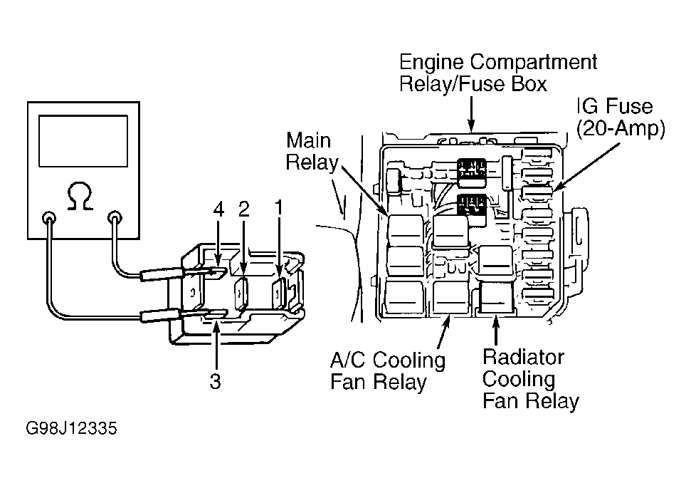
- Observe main relay (located in engine compartment relay/fuse block) while ignition is cycled on, then off. See Fig 1
. If sound is heard at relay, turn ignition off. Disconnect ECM harness connectors and go to step 6
. If no sound is heard, go to next step.
 Courtesy of SUZUKI OF AMERICA CORP.
- Ensure ignition if off. Remove main relay. Measure resistance between relay terminals No. 3 and 4. See Fig 1
. Resistance should be 70-110 ohms. If resistance is as specified, go to next step. If resistance is not as specified, replace relay.
- Check for continuity between terminals No. 1 and 2. Continuity should not exist. Apply battery voltage to terminal No. 3 and ground to terminal No. 4. Continuity should exist between terminals No. 1 and 2. If continuity is not as specified, replace relay. If continuity is as specified, go to next step.
- Ensure LAMP fuse (60-amp) in engine compartment relay/fuse block is okay. If fuse is blown, check for short to ground and repair as necessary. If fuse is okay, go to next step.
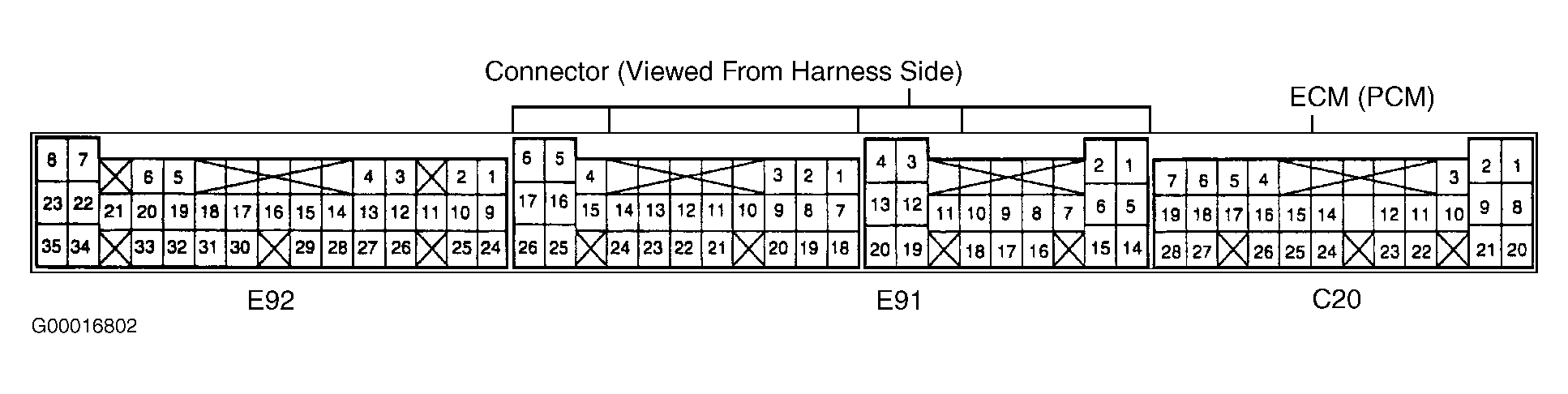
- Turn ignition off. Install main relay. Disconnect ECM harness connectors. Check ECM harness connector E92 terminals No. 8, 10 and 23 and ECM harness connector C20 terminal No. 7 for proper contact. See Fig 2
. If poor terminal contact is found, repair as necessary and retest system. If connection is okay, go to next step.
 Courtesy of SUZUKI OF AMERICA CORP.
- Turn ignition on. Measure voltage between ground and ECM harness connector C20 terminal No. 7 (Black/White wire) and connector E92 terminal No. 10 (Green wire). If readings are 10-14 volts on both circuits, go to next step. If readings are not 10-14 volts on both circuits, repair open in Black/White wire between LAMP fuse (60-amp) and main relay, or open in Green wire between main relay and ECM. Repair as necessary.
- Using a fused jumper wire, ground ECM harness connector E92 terminal No. 10 (Green wire). Turn ignition on. Measure voltage between ground and ECM harness connector E92 terminal No. 8 (Red/Black wire). If reading is 10-14 volts, go to next step. If reading is not 10-14 volts, repair open in Red wire between FI fuse (15-amp) and main relay, or open in Red/Black wire between ECM and main relay.
- Check for open in Blue/White or Black/Orange wire (ECM ground wires). Repair as necessary. If wires are okay, replace ECM. Retest system.