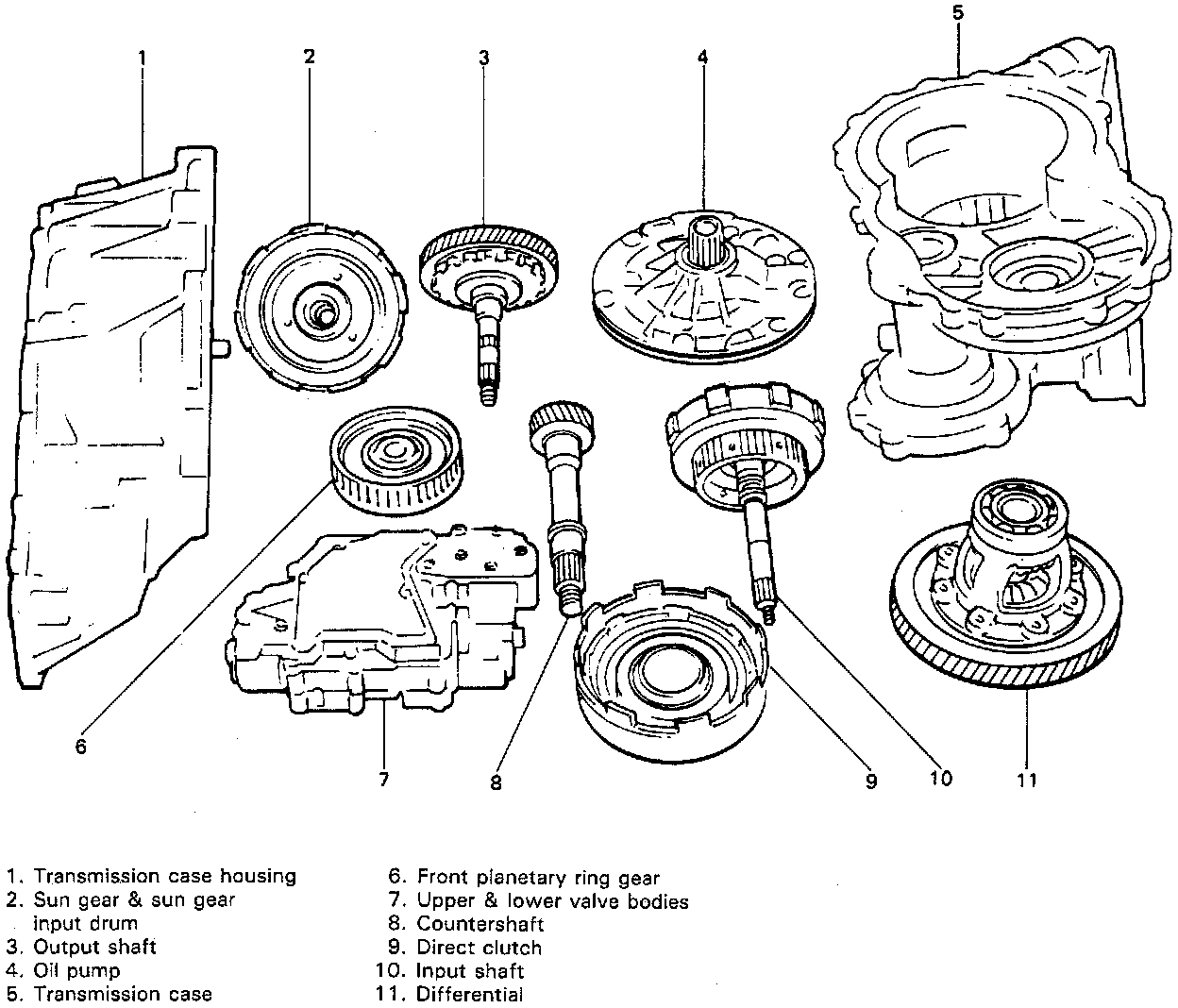
Part 1
DISASSEMBLYCAUTION:
^ Thoroughly clean transmission exterior before overhauling it.
^ Keep working table, tools and hands clean while overhauling.
^ Use special care to handle aluminum parts so as not to damage them.
^ Do not expose removed parts to dust. Keep them clean always.
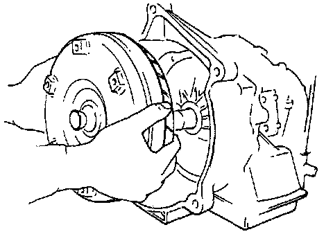
1. Remove torque converter.
2. Remove engine mounting LH bracket.
3. Remove oil level gauge and oil filler tube.
4. Drain transmission fluid. To drain fluid better, tilt transmission in various directions.
5. Remove oil pan and oil pan gasket.
NOTE:
^ For removal of oil pan, do not turn transmission over as this will contaminate valve body with foreign matters in the bottom of oil pan.
^ When removing oil pan, tap around it lightly with a plastic hammer. Do not force it off by using a screwdriver or the like.
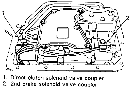
6. Disconnect couplers of direct clutch and 2nd brake solenoid valves.
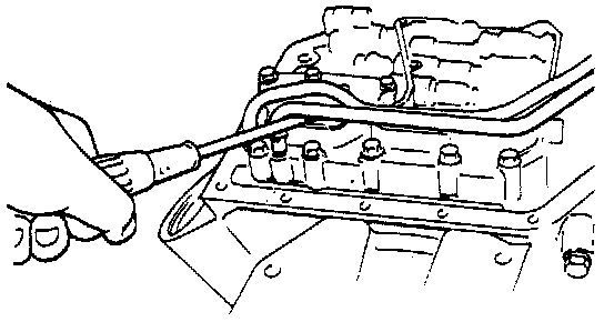
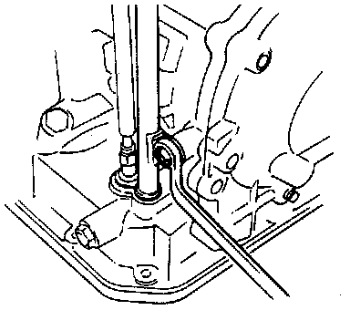
7. Remove 2 oil tubes from lower valve body. Remove them by pulling up tube end with a screwdriver.
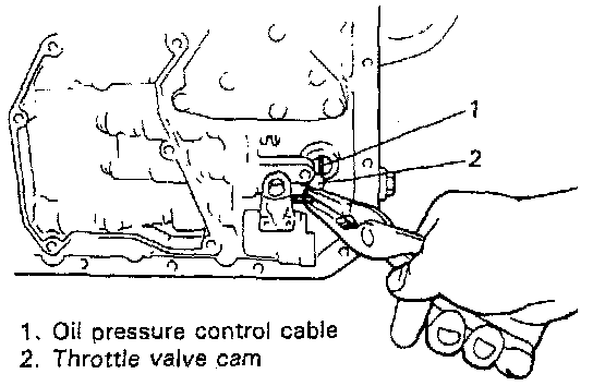
8. Disconnect oil pressure control cable from throttle valve cam and then remove cable.
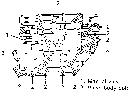
9. Remove oil strainer and lower valve body. For removal of lower valve body, remove 11 bolts shown in figure.
CAUTION: Be careful not to let manual valve fall off when removing valve body assembly.
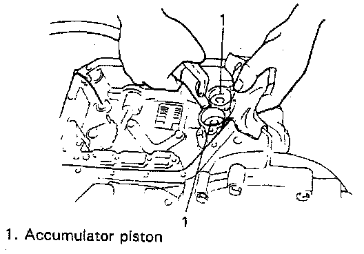
10. Remove second brake accumulator upper spring and remove accumulator pistons and springs. Position a rag on pistons to catch each piston. To remove pistons, force low-pressure compressed air (1 kg/cm2, 15 psi, 100 kPa, max) into hole as shown, and pop each piston into the rag.
NOTE: Do not push accumulator pistons with fingers or anything before removing them. Pushing them may cause compressed fluid in accumulator to spew out of hole at face and clothes.
11. Remove second brake band cover and gasket.
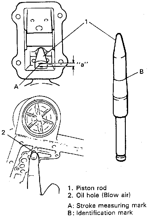
12. After removing second brake band cover, check second brake piston stroke as follows.
(1) Scribe mark on piston rod as shown in figure.
(2) Blow air into oil hole and measure rod stroke.
(3) If stroke is out of specification, replace piston rod with the one of different length or replace second brake band. 2nd brake piston rod of 2 different lengths are available as spare parts.
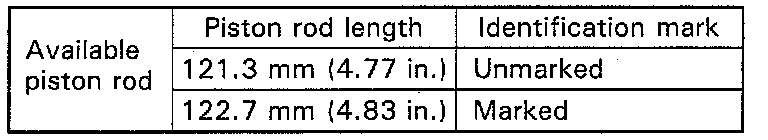
Piston rod stroke "a": 1.5 - 3.0 mm (0.06 - 0.11 inch)
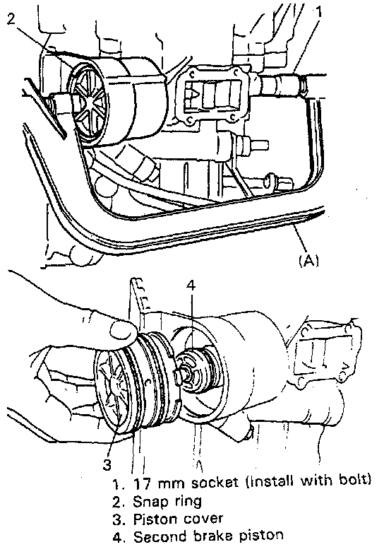
13. Remove second brake piston.
(1) Install 17 mm socket with 8 mm bolt.
(2) Apply valve lifter as illustrated and push in piston cover.
Special Tool
(A): 09916-14510
(3) Remove snap ring by using screwdriver(s) or the like.
(4) Remove tools and take out 2nd brake piston cover and piston. Tap cover head lightly to pull out cover.
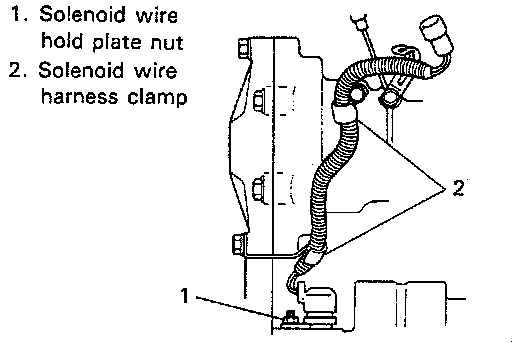
14. Remove solenoid wire harness.
(1) Remove wire hold plate securing nut.
(2) Remove 2 wire clamps on transmission and pull out solenoid wire.
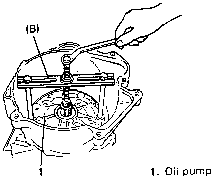
15. Remove oil pump.
(1) Remove 6 oil pump securing bolts.
(2) Remove oil pump by using special tool.
CAUTION: Make sure that 2nd brake piston and piston rod have been removed before oil pump removal. If not, they may cause breakage of 2nd brake band.
Special Tool
(B): 09918-48210
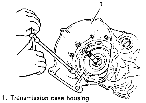
16. Remove transmission case housing.
(1) Remove housing internal bolts and external bolts.
(2) Remove housing while tapping around it lightly with a plastic hammer.
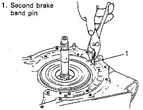
17. Remove second brake band pin.
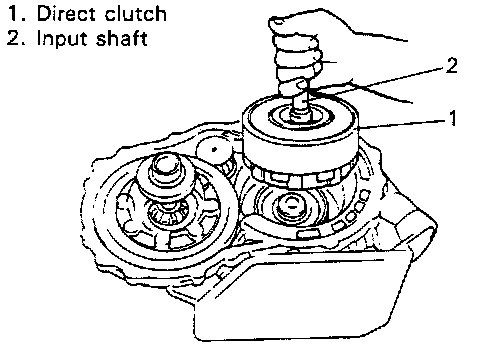
18. Remove direct clutch and forward clutch at the same time while holding input shaft.
NOTE: Be careful not to loose ring gear race and bearing which may sometimes stick to input shaft.
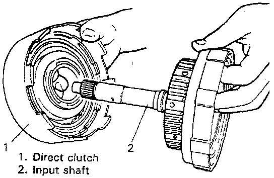
19. Remove direct clutch assembly from input shaft.
20. Remove second brake band.
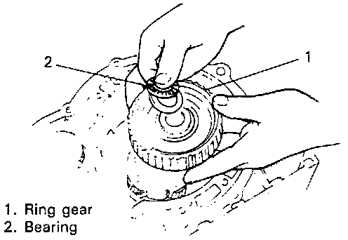
21. Remove front planetary ring gear and ring gear bearing.
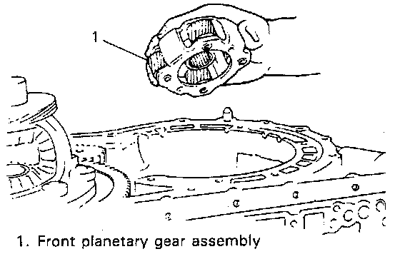
22. Remove front planetary gear assembly.
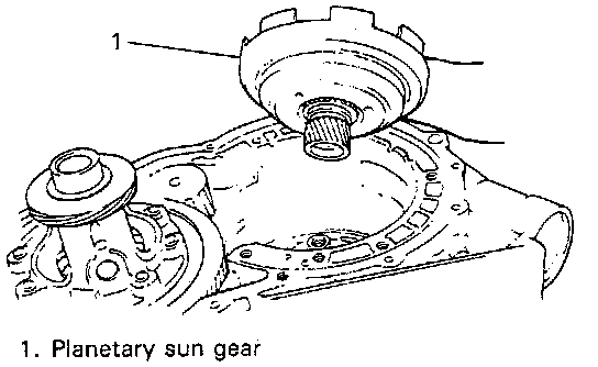
23. Remove planetary sun gear and front planetary gear bearing.
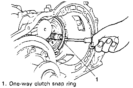
24. Remove one way clutch snap ring by using a screwdriver.
NOTE: Use care not to damage transmission case when removing snap ring.
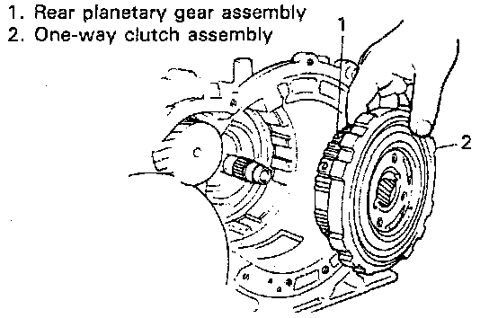
25. Remove one way clutch and rear planetary gear.
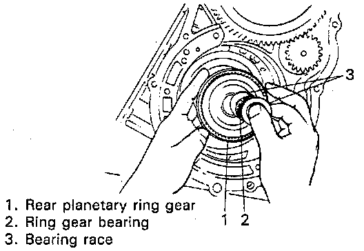
26. Remove rear planetary ring gear, ring gear bearing and washers.
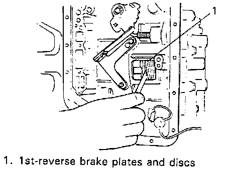
27. Check 1st-reverse brake clearance. Measure clearance between snap ring and flange with feeler gauge. If out of specification, replace 1st-reverse brake discs or plates.
1st-reverse brake clearance 0.58 - 1.92 mm (0.023 - 0.075 inch)
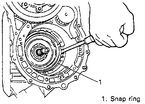
28. Remove 2 snap rings by using a flat tip screwdriver.
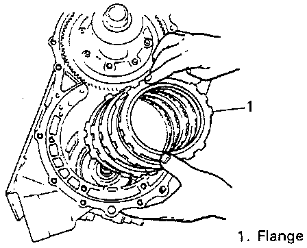
29. Remove 1st-reverse brake flange, discs, plates and damper plate.
30. Remove differential gear assembly.
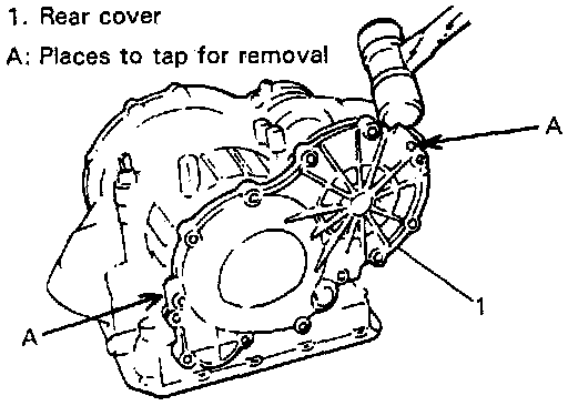
31. Remove rear cover.
(1) Remove 10 bolts and 2 nuts.
(2) Remove rear cover by tapping A with plastic hammer as shown in figure.
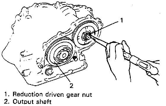
32. Remove reduction driven gear nut.
(1) Undo caulking.
(2) Shift manual shift lever to "P" so that output shaft is locked.
(3) Loosen nut.
CAUTION: Calmly apply torque to loosen nut so as not to damage reduction gear or parking lock pawl.
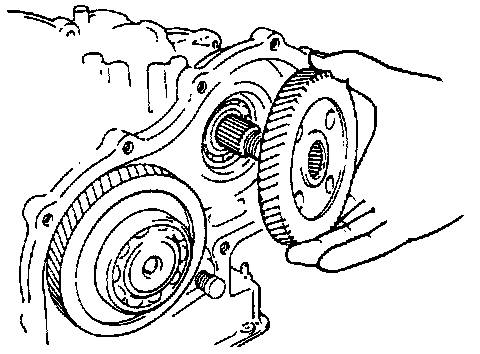
33. Pull out reduction driven gear.
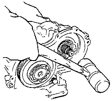
34. Drive countershaft out with a plastic hammer.
CAUTION: To avoid unnecessary damage of speed sensor due to contact with countershaft gear, it should be removed previously.
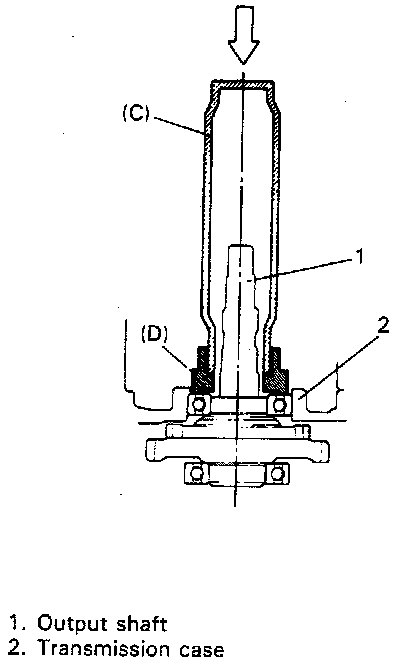
35. Remove output shaft by pushing outer race of internal output shaft bearing with special tools from inside of transmission case.
CAUTION:
^ Do not hit output shaft or shaft end will be damaged.
^ Hold special tools by hand while hitting them and avoid their bounce.
Special Tool
(C): 09925-18010
(D): 09927-08210
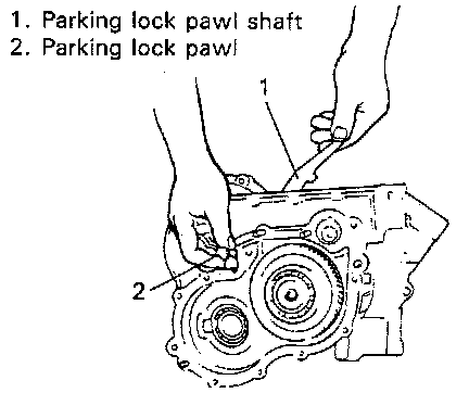
36. Remove parking lock pawl, pawl shaft and sleeve, etc.
(1) Pull out parking lock pawl shaft and spring.
(2) Remove parking lock pawl.
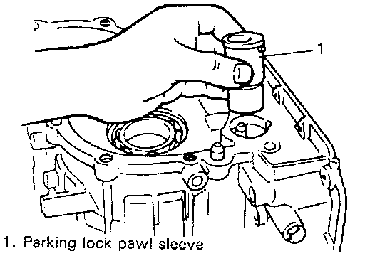
(3) Pull out parking lock pawl sleeve.
(4) Remove manual detent spring assembly and manual shift shaft.
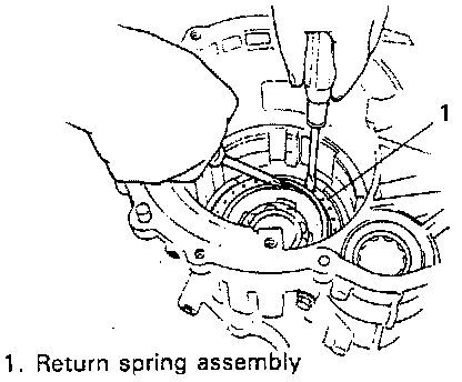
37. Remove 1st-reverse brake piston.
(1) Push down return spring assembly and remove snap ring.
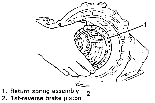
(2) Take out return spring assembly.
(3) By blowing air, push out 1st-reverse brake piston.
CAUTION:
^ Blow air very carefully, or outer O ring will be damaged.
^ Pull out piston by using long nose pliers, if failed to remove it by air blow.
^ Without replacing O-rings prepared, do not attempt to remove piston.
CLUTCH AND BRAKE PARTS DIAGNOSIS
Clutch Discs and Brake Band
Dry and inspect them for pitting, flaking, wear, glazing, cracking, charring and chips or metal particles imbedded in lining. If discs or brake band show any of the above conditions, replacement is required.
Clutch Steel Plates
Dry plates and check for discoloration. If plate surface is smooth and even color smear is indicated, the plate should be reused. If severe heat spot discoloration or surface scuffing is indicated, the plate must be replaced.
Clutch or Brake Return Spring Assembly
Evidence of extreme heat or burning in the area of clutch may have caused springs to take a heat set and would require their replacement.
Possible Causes Of Burning
Forward and Direct Clutch Discs
- Stuck or leak in check ball in clutch piston.
- Damaged clutch piston seals.
- Worn or broken seal rings.
- Obstruction in solenoid valves or shift valves.
- Disconnected speed sensor, solenoid or controller.
- Leak in valve body gaskets.
- Low line pressure.
1st/REV Brake Discs and 2nd Brake Band
- Damaged piston seals.
- Obstruction in solenoid valves or shift valves.
- Leak in valve body gaskets.
- Low line pressure.
SUB ASSEMBLY SERVICE
CAUTION:
^ Keep component parts in group for each sub assembly and avoid mixing them up.
^ Clean all parts with cleaning solvent thoroughly and air dry them.
^ Use kerosene or automatic transmission fluid as cleaning solvent.
^ Do not use wiping cloths or rags to clean or dry parts.
^ All oil passages should be blown out and checked to make sure that they are not obstructed.
^ Keep face and eyes away from solvent spray while air blowing parts.
^ Check mating surface for irregularities and remove them, if any, and clean it again.
^ Soak new clutch discs and brake band in transmission fluid for 2 hours or more before assembly.
^ Replace all gaskets and O-rings with new ones.
^ Apply automatic transmission fluid to all O-rings except oil pump cover seal.
^ When installing seal ring, be careful so that it is not expanded excessively, extruded or caught.
^ Replace oil seals that are removed and apply grease to their lips.
^ Before installing, be sure to apply automatic transmission fluid to sliding, rolling and thrusting surface of all component part. Also after installation, make sure to check each part for proper operation.
^ Always use torque wrench when tightening bolts.
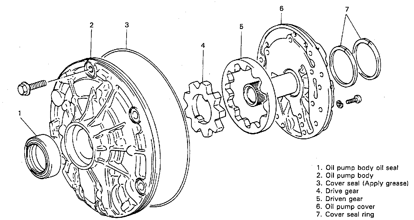
Oil Pump
Removal
1. Remove 2 oil pump cover seal rings.
2. Remove oil pump cover seal (O ring).
3. Remove 11 bolts.
4. Remove oil pump cover.
Inspection
1. Inspect pump body oil seal. Check for wear, damage or cracks. Replace oil seal if necessary and apply grease to its lip portion slightly when it is installed.
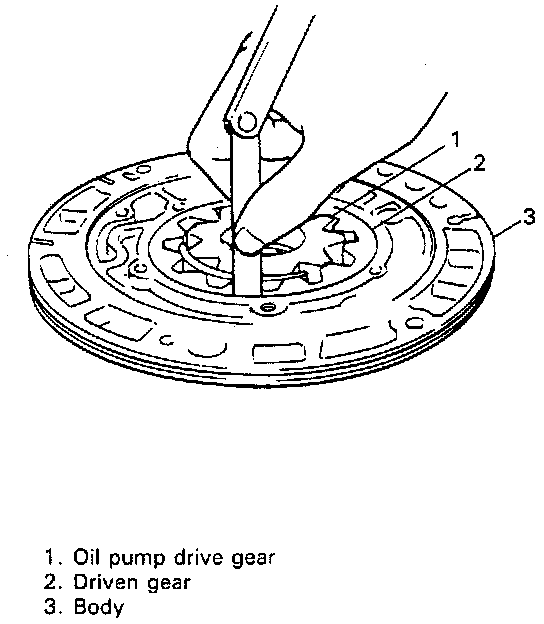
2. Check body clearance of driven gear. Push driven gear to one side of body. Using a feeler gauge, measure clearance between driven gear and body. If clearance exceeds its limit, replace gear.
Body clearance
Standard: 0.07 - 0.15 mm (0.0028 - 0.0059 inch)
Limit: 0.3 mm (0.011 inch)
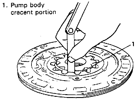
3. Check tip clearance of both drive and driven gears. Measure radial clearance between gear tooth and crescent. If clearance exceeds its limit, replace gear.
Tip clearance
Standard: 0.11 - 0.14 mm (0.0044 - 0.0055 inch)
Limit : 0.3 mm (0.011 inch)
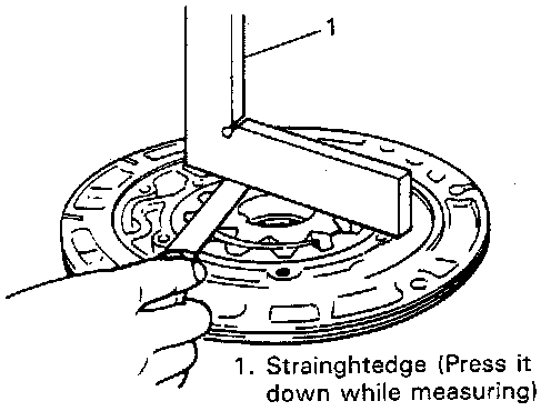
4. Check side clearance of both gears. Using a straightedge and a feeler gauge, measure side clearance between gear and pump body.
Side clearance
Standard: 0.02 - 0.05 mm (0.0008 - 0.0019 inch)
Limit: 0.1 mm (0.0039 inch)
Installation
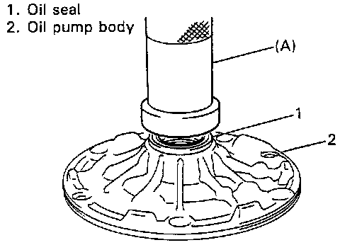
1. Install pump body oil seal. Use special tool and hammer to install it, and then apply grease to its lip portion.
Special Tool (A): 09913-85210
2. Install driven gear and drive gear to pump body after applying fluid to gears.
3. Install pump cover to pump body and tighten 11 pump cover bolts to specification.
Tightening Torque (a): 8 - 12 Nm (0.8 - 1.2 kg-m, 6.0 - 8.5 ft. lbs.)
4. Install 2 oil pump cover seal rings.
5. Apply transmission fluid to oil pump bushes and 2 seal rings.
6. Install cover seal (O ring) applied with grease and make sure that it is not twisted or extruded.
7. Check drive gear for smooth rotation.
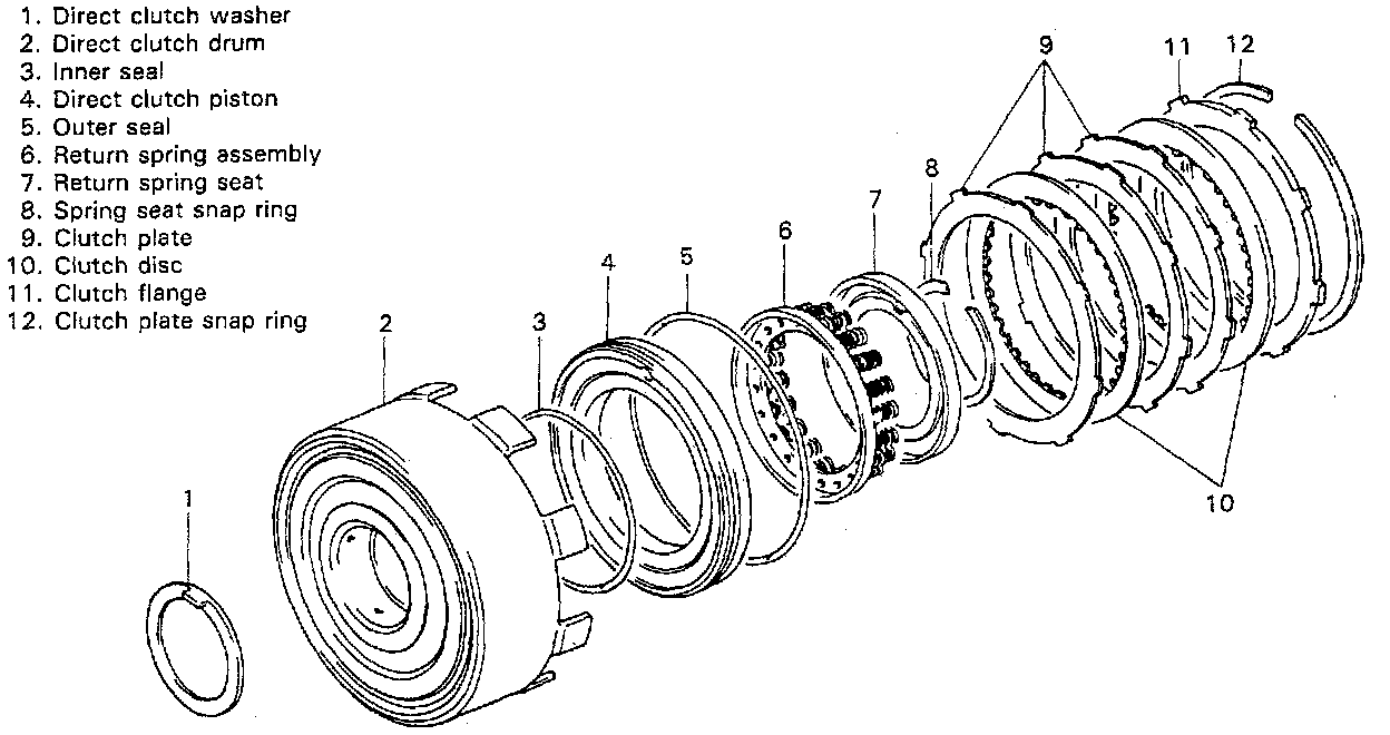
Direct Clutch
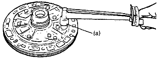
Preliminary Check
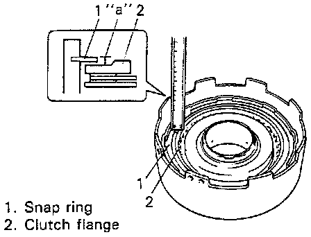
Check direct clutch clearance before disassembly. For checking clearance, measure height between snap ring and clutch flange by using vernier as shown in figure. If height is within specification, it means that clutch clearance is within specification. If height is out of specification, replace clutch discs or plates with new ones.
Height "a": 2.49 - 3.06 mm (0.098 - 0.120 inch)
Removal
1. Remove clutch plate snap ring.
2. Remove clutch flange, discs and plates.
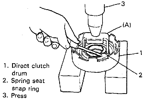
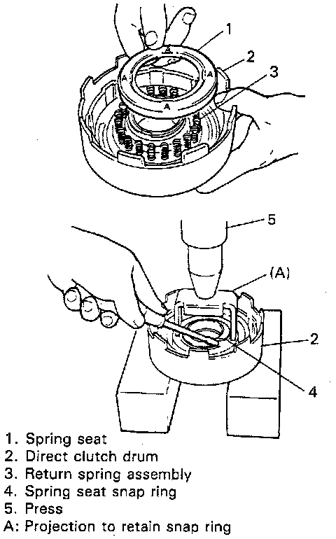
3. Remove spring seat snap ring. Compress piston return springs by using special tool and then remove snap ring.
Special Tool (A): 09926-98310
CAUTION: Do not compress spring seat too much. Excessive compression may cause spring seat to become distorted.
4. Remove spring seat and return spring assembly.
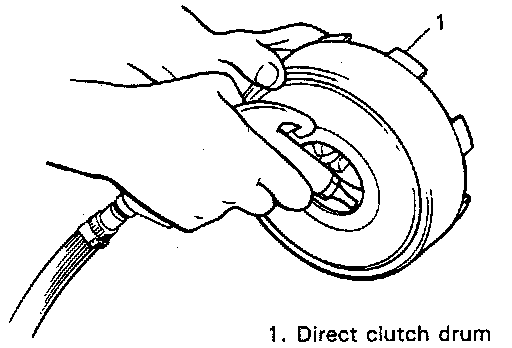
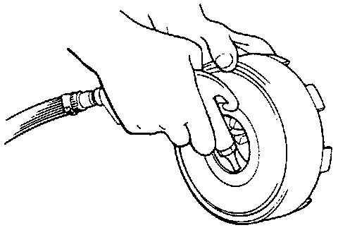
5. Remove direct clutch piston. Blow compressed air through drum oil hole to remove piston. If piston does not pop out, take out piston with long nose pliers.
6. Remove inner seal from drum.
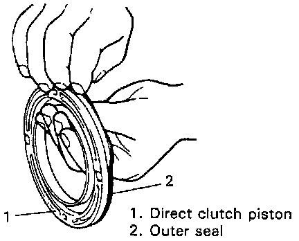
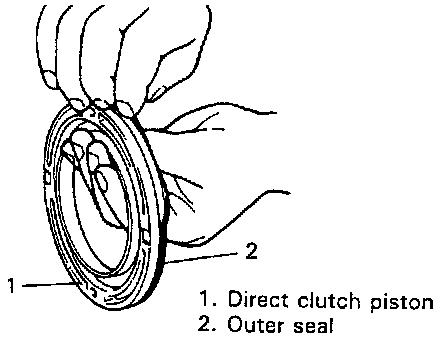
7. Remove outer seal from piston.
Inspection
1. Check valve (steel ball) for free movement in piston.
2. Check valve for leakage by using low pressure air. If found faulty, replace piston.
Installation
1. Install inner seal (O ring). Apply transmission fluid to inner seal and fit it in drum. Use new inner seal.
2. Install outer seal (O ring). Apply transmission fluid to outer seal and fit it to piston. Use new outer seal.
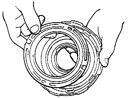
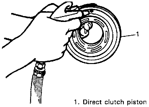
3. Install piston into drum. Be careful so that seals (O-rings) do not get twisted or caught.
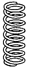
4. Install clutch return spring assembly.
5. Install spring seat.
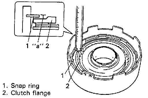
6. Install snap ring. Compress return springs and install spring seat snap ring in groove. Place special tool (clutch spring compressor) on spring seat and compress springs with press, and then, install snap ring using a screwdriver.
Special Tool (A): 09926-98310
CAUTION:
^ Check to make sure that snap ring is securely fitted in 4 projections A of spring seat.
^ Do not compress return spring more than necessary.
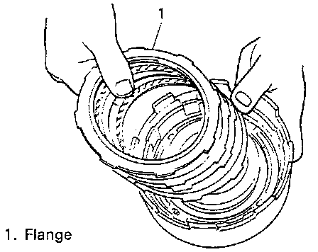
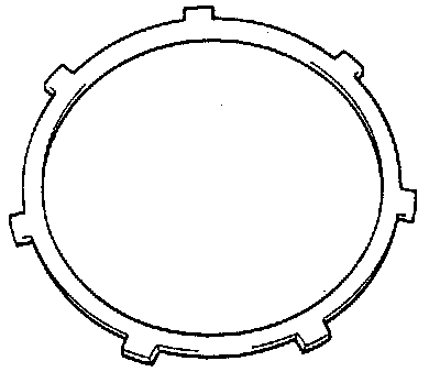
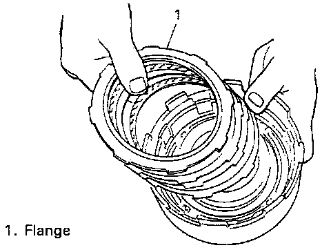
7. Install discs, plates and flange in the following order.
(1) Plate, (2) Disc, (3) Plate, (4) Plate, (5) Disc, (6) Flange
NOTE: If new clutch discs are installed, soak them in automatic transmission fluid for 2 hours or more before assembly.
8. Install clutch plate snap ring.
9. After installing clutch plate snap ring, measure height between snap ring and clutch flange as previously outlined. If height is out of specification even when new clutch discs and plates are installed, install flange of different thickness. Following 2 types of clutch flanges are available as spare parts.
Height "a": 2.49 - 3.06 mm (0.098 - 0.120 inch)
10. Check piston for movement by blowing air through air hole in drum.
CAUTION: Apply only low pressure air for checking movement. Excessive air pressure may cause damage to spring seat.