Differential Axle Housing: Service and Repair
REMOVAL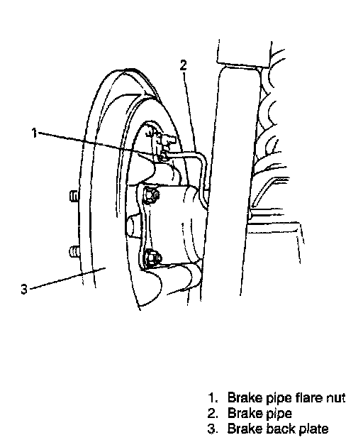
1. Drain differential gear oil.
Carry out steps 2 to 8 and 16 to 19 on both right and left wheels.
Note that left wheel and its related parts are used in illustrations in this section.
2. Remove rear brake drum. (Refer to steps 1 to 5 of Brake Drum Removal in Brakes and Traction Control.)
3. Disconnect brake pipe from wheel cylinder. With right side wheel cylinder, disconnect 2 brake pipes.
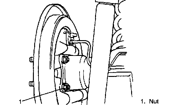
4. Remove rear wheel bearing retainer nuts from rear axle housing.
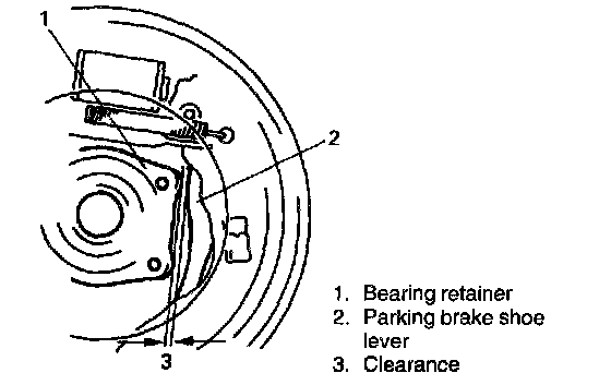
5. Check to ensure that there is clearance between rear wheel bearing retainer and parking brake shoe lever. If no clearance is found, loosen cable locking nut further to obtain clearance.
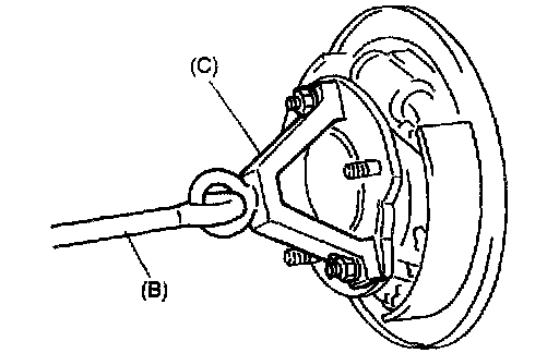
6. Using special tools (B) & (C) indicated below, draw out axle shafts. For vehicle equipped with ABS, remove wheel speed sensor from axle housing before drawing out axle shaft.
NOTE: Use care not to pull brake back plate along with shaft.
Special Tool
(C): 09943-35511
(B): 09942-15510
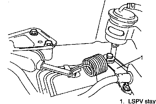
7. Remove LSPV stay from axle housing (if equipped with LSPV).
8. Remove brake back plate from rear axle housing.
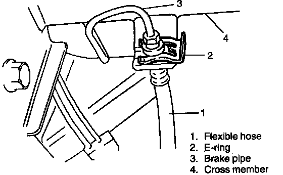
9. Disconnect brake pipe from flexible hose and remove E-ring (front side).
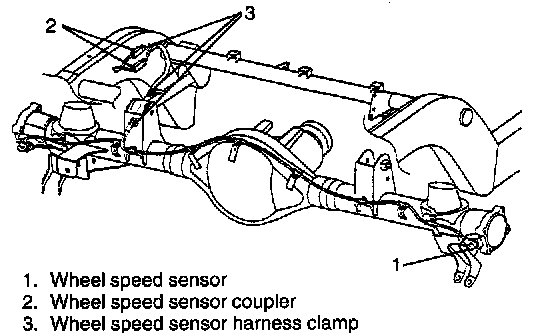
10. For vehicle with ABS, disconnect wheel speed sensor coupler and remove harness clamp from chassis frame.
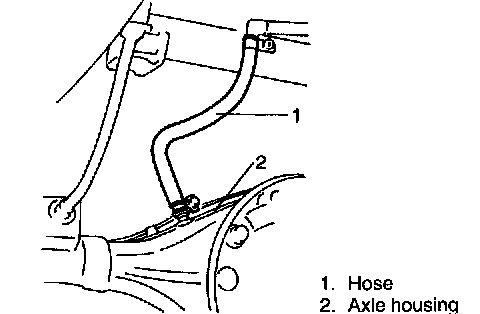
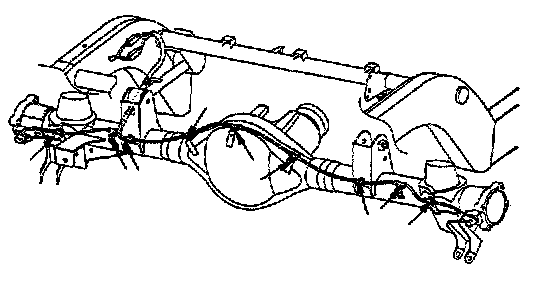
11. Remove brake pipe clamps and pipes from axle housing and disconnect breather hose from axle housing.
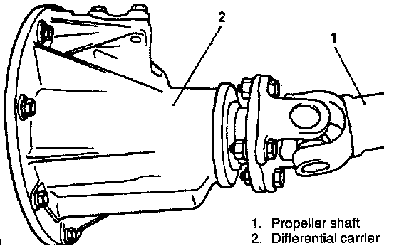
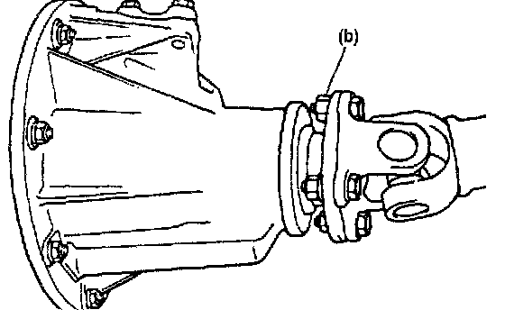
12. Disconnect propeller shaft and remove propeller shaft from transmission.
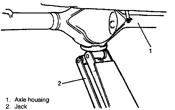
13. For jobs hereafter, support rear axle housing by using floor jack under axle housing.
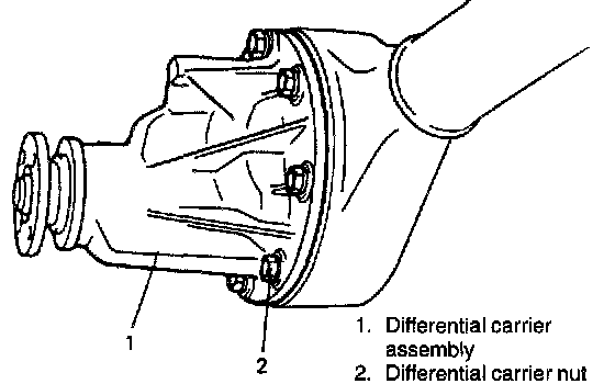
14. Remove differential carrier assembly.
15. Loosen rear mount nut of upper rod but don't remove bolt.
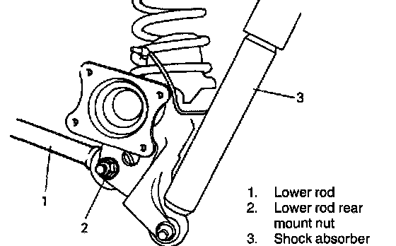
16. Loosen rear mount nut of lower rod but don't remove bolt.
17. Remove rear axle side lateral rod mount bolt.
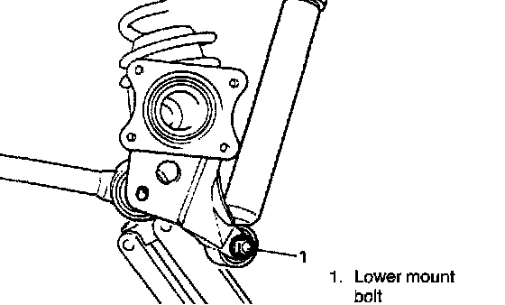
18. Remove shock absorber lower mount bolt.
19. Remove wheel speed sensor harness from axle housing, if equipped with ABS.
20. Lower floor jack until tension of suspension coil spring becomes a little loose and remove rear mount bolt of upper, lower and lateral rod.
21. Lower rear axle housing gradually.
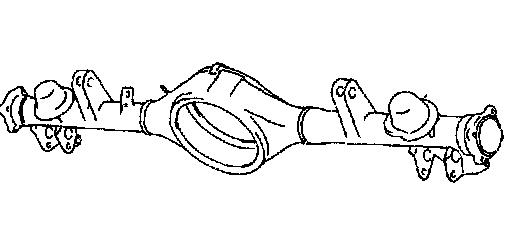
22. Remove axle housing.
INSTALLATION
Install removed parts in reverse order of removal, noting the following.
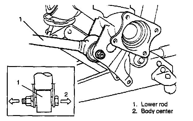
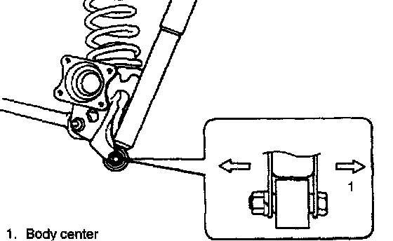
1. Place rear axle housing on floor jack. Then install upper/lower rod rear mounting bolts (right & left) in proper direction as shown. At this time, mount nuts but don't tighten them.
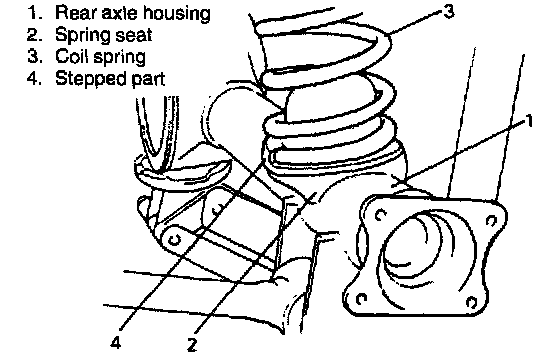
2. Install coil spring (right & left) on spring seat of axle housing and raise axle housing.
NOTE: When seating coil spring, mate spring end with stepped part of rear axle spring seat as shown.
3. Install lateral rod to rear axle housing.
4. Install lower part of shock absorber to right and left sides of axle housing and install bolts in proper direction as shown in figure.
At this time, mount nuts but don't tighten them.
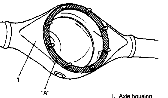
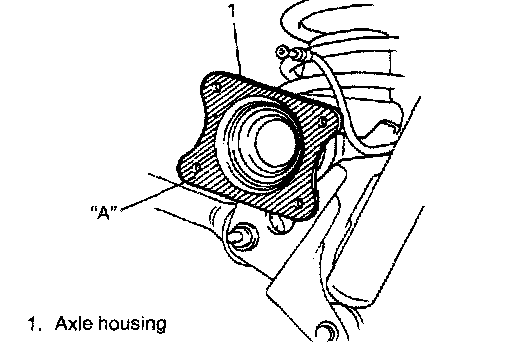
5. Clean mating surfaces of axle housing and differential carrier and apply sealant to housing side.
"A": Sealant 99000-31110
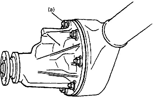
6. Install differential carrier assembly to axle housing and tighten carrier nuts to specified torque.
Tightening Torque (a): 55 Nm (5.5 kg-m, 40.0 ft. lbs.)
7. For vehicle with ABS, connect wheel speed sensor coupler and install harness.
8. Install propeller shaft and torque nuts to specification.
Tightening Torque (b): 50 Nm (5.0 kg-m, 36.5 ft. lbs.)
9. Remove floor jack from axle housing and connect breather hose onto axle housing and clamp it securely.
10. Connect brake pipes onto axle housing and clamp them securely.
For clamping positions, refer to Brakes and Traction Control.
11. Connect brake flexible hose to bracket on axle housing and secure it with E-ring.
12. Install LSPV stay to axle housing, tighten LSPV stay bolt to specified torque.
And adjust LSPV referring to LSPV Assembly Inspection And Adjustment in Brakes and Traction Control.
Tightening Torque (c): 10 Nm (1.0 kg-m, 7.5 ft. lbs.)
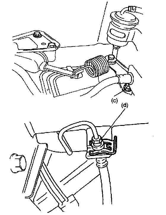
13. Connect brake pipe to brake flexible hose and tighten brake pipe flare nut to specified torque.
Tightening Torque (d): 16 Nm (1.6 kg-m, 11.5 ft. lbs.)
14. Clean mating surface of axle housing (right & left) and brake back plate, then apply sealant as shown.
"A": Sealant 99000-31110
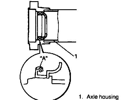
15. Apply grease to axle shaft inner oil seal lip as shown.
"A": Grease 99000-25010
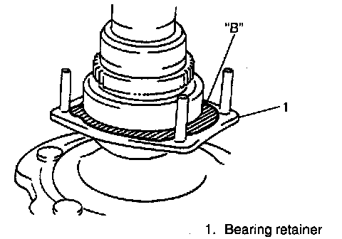
16. Apply sealant to mating surface of bearing retainer with brake back plate.
NOTE: Make sure to remove old sealant before applying it anew.
"B": Sealant 99000-31110
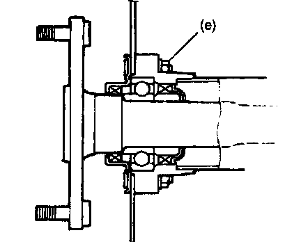
17. Install rear axle shaft to rear axle housing and tighten bearing retainer nuts to specified torque.
NOTE: When installing rear axle shaft, be careful not to cause damage to oil seal lip in axle housing.
Tightening Torque (e): 23 Nm (2.3 kg-m, 17.0 ft. lbs.)
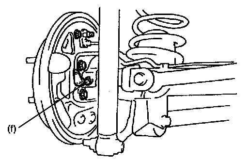
18. Tighten wheel speed sensor bolt to specified torque.
Tightening Torque (f): 21 Nm (2.1 kg-m, 15.5 ft. lbs.)
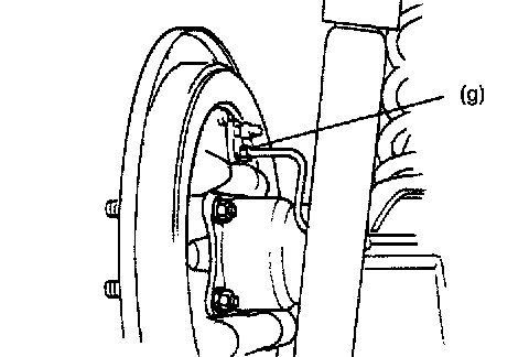
19. Connect brake pipes to wheel cylinders (right & left) and tighten brake pipe flare nuts to specified torque.
Tightening Torque (g): 16 Nm (1.6 kg-m, 11.5 ft. lbs.)
20. Install brake drum (right & left). For details, refer to Brakes and Traction Control.
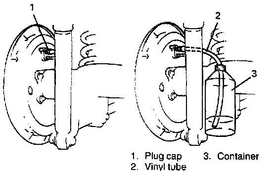
21. Refill differential gear housing with new specified gear oil.
22. Fill reservoir with brake fluid and bleed brake system.(For bleeding operation, refer to Brakes and Traction Control.)
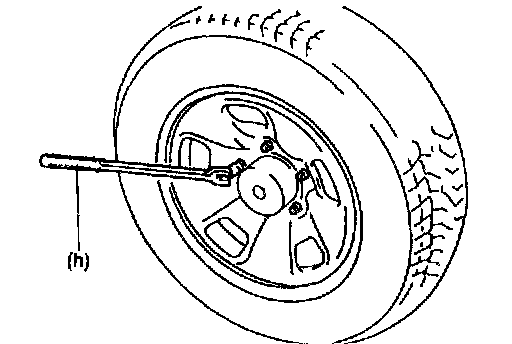
23. Install wheel and tighten wheel nuts to specified torque.
Tightening Torque (h): 95 Nm (9.5 kg-m, 69.0 ft. lbs.)
24. Upon completion of all jobs, depress brake pedal with about 30 kg (66 lbs) load three to ten times so as to obtain proper drum-to-shoe clearance.
Adjust parking brake cable (for adjustment, refer to Brakes and Traction Control.)
25. Tighten parking brake lever cover screws.
26. Lower hoist.
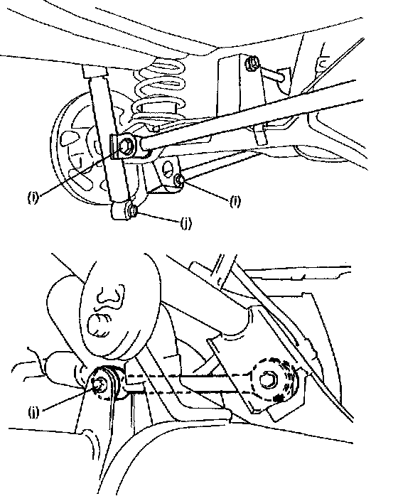
27. Tighten right and left lower/upper rod nuts lateral rod mount bolt and shock absorber nuts to specified torque.
NOTE: When tightening these nuts, be sure that vehicle is off hoist and in non loaded condition.
Tightening Torque:
(i): 90 Nm (9.0 kg-m, 65.0 ft. lbs.)
(j): 85 Nm (8.5 kg-m, 61.5 ft. lbs.)
28. Check to ensure that brake drum is free from dragging and proper braking is obtained.
29. Perform brake test (foot brake and parking brake).
30. Check each installed part for oil leakage.