On-Board Diagnostic System Description
AUTOMATIC TRANSMISSION DIAGNOSISThis vehicle is equipped with an electronic transmission control system, which control the automatic shift up and shift down timing, TCC operation, etc. suitably to vehicle driving conditions.
PCM (ECM) has an On-Board Diagnosis system which detects a malfunction in this system and abnormality of those parts that influence the engine exhaust emission.
When diagnosing a trouble in the transmission including this system, be sure to have full understanding of the outline of "On-Board Diagnostic System" and each item in "Precaution in Diagnosing Trouble" and execute diagnosis according to "AUTOMATIC TRANSMISSION DIAGNOSTIC FLOW TABLE" to obtain correct result smoothly.
ON-BOARD DIAGNOSTIC SYSTEM
For automatic transmission control system, PCM (ECM) has following functions.
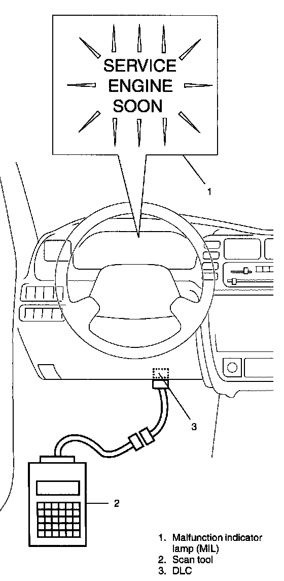
^ When the ignition switch is turned ON with the engine at a stop, Malfunction Indicator Lamp (MIL) turns ON to cheek the bulb of the MIL.
^ When PCM detects a malfunction in A/T control system (and/or a malfunction which gives an adverse effect to vehicle emission) while the engine is running, it makes the malfunction indicator lamp in the meter cluster of the instrument panel turn ON and stores the malfunction area (DTC according to SAE J2012) in its memory.
(If it detects that continuously 3 driving cycles are normal after detecting a malfunction, however, it makes MIL turn OFF although DTC stored in its memory will remain)
^ It is possible to communicate through DLC by using not only SUZUKI scan tool (Tech-1) but also OBD-II generic scan tool which are in compliance with SAEJ1978. (Diagnostic information can be accessed by using a scan tool.)
2 DRIVING CYCLE DETECTION LOGIC
PENDING DTC
FREEZE FRAME DATA
PRECAUTION IN DIAGNOSING TROUBLE
^ Don't disconnect couplers from PCM (ECM), battery cable from battery, PCM ground wire harness from engine or main fuse before checking the diagnosis information (DTC, freeze frame data, etc.) stored in PCM memory. Such disconnection will clear memorized information in PCM memory.
^ Using SUZUKI scan tool (Tech-1) or OBD-II generic scan tool, the diagnostic information stored in PCM memory can be checked and cleared as well. Before its use, be sure to read Operator's (Instruction) Manual supplied with it carefully to have good understanding of its functions and usage.
^ Priorities for diagnosing troubles
If troubleshooting priorities for multiple diagnostic codes are given in the applicable DTC flow table, these should be followed. If no instructions are given, troubleshoot diagnostic trouble codes according to the following priorities.
1. Diagnostic trouble codes (DTCs) other then DTC P0171/P0172/ P0174/P0175 (Fuel system too lean/too rich), DTC P0300/P0301/P0302/P0303/P0304/P0305/P0306 (Misfire detected) and DTC P0400 (EGR flow malfunction)
2. DTC P0171/P0172/P0174/P0175 (Fuel system too lean/too rich) and DTC P0400 (EGR flow malfunction)
3. DTC P0300/P0301/P0302/P0303/P0304/P0305/P0306 (Misfire detected)
^ PCM replacement
When substituting a known-good PCM, check for following conditions. Neglecting this check may result in damage to a good PCM.
- All relays and actuators have resistance of specified value.
- MOP sensor, TP sensor and fuel tank pressure sensor are in good condition. Also, the power circuit of these sensors is not shorted to the ground.