Part 2
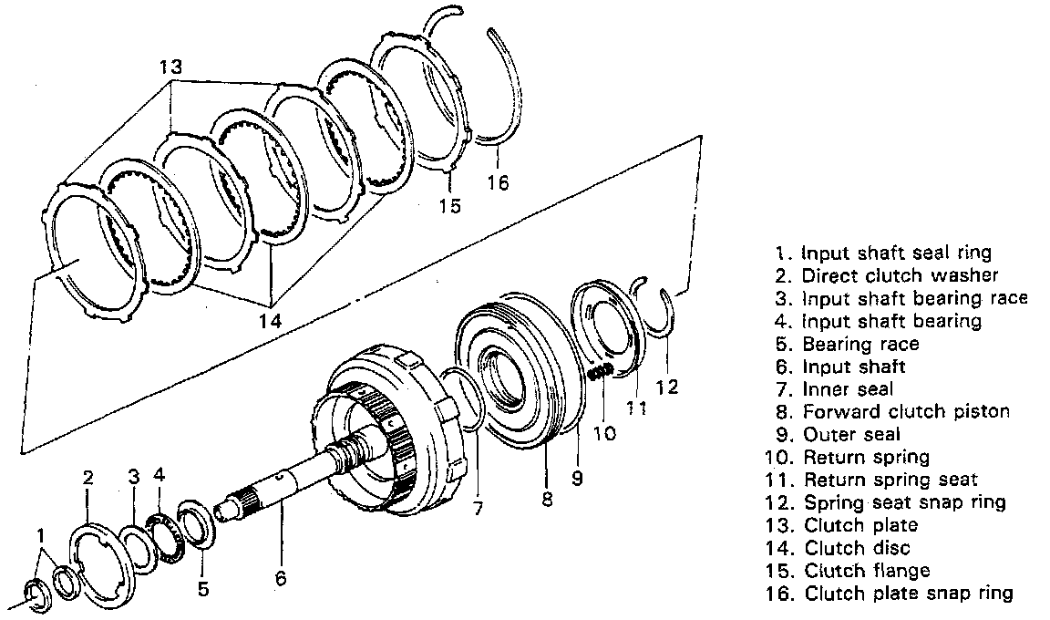
Forward Clutch
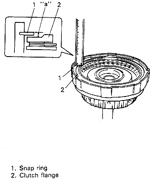
Preliminary Check
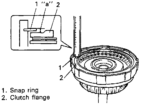
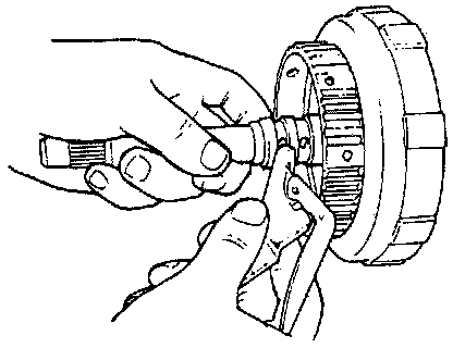
Check forward clutch clearance before disassembly. For checking clearance, measure height between snap ring and clutch flange by using vernier as shown in figure. If height is within specification, it means that clutch clearance is within specification. If height is out of specification, replace clutch discs or plates with new ones.
Height "a": 2.01 - 2.68 mm (0.079 - 0.105 inch)
Removal
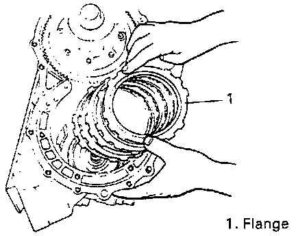
1. Remove clutch plate snap ring.
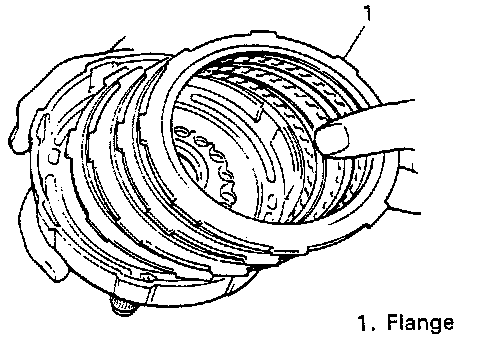
2. Remove flange, discs and plates.
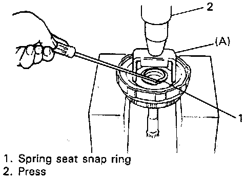
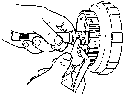
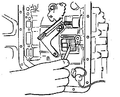
3. Remove seat snap ring. Compress piston return springs and remove snap ring. Place special tool (clutch spring compressor) on spring seat and compress spring with a press, and then, remove snap ring, using a screwdriver.
Special Tool (A): 09926-98310
CAUTION: Do not push down return spring more than necessary.
4. Remove spring seat and springs.
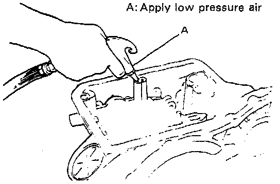
5. Remove forward clutch piston. Blow compressed air through input shaft oil hole to remove piston. If piston does not pop out, take it out with long nose pliers.
6. Remove inner and outer seals (O-rings) from piston.
Inspection
1. Check valve (ball) for free movement in clutch piston.
2. Check valve for leakage by using low pressure air. If found faulty, replace clutch piston.
Installation
1. Install inner and outer seals (O-rings) to clutch piston. Apply transmission fluid to them and fit to piston. Use new seals.
2. Install piston into input shaft drum. Use care so that seals do not get twisted or caught.
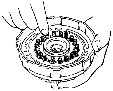
3. Install 18 piston return springs and spring seat.
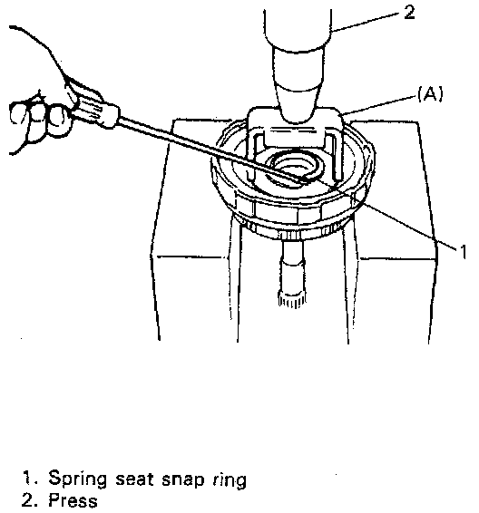
4. Install spring seat snap ring. Compress return springs and install snap rings in groove by using a screwdriver. Place special tool (clutch spring compressor) on spring seat and compress springs with a press.
Special Tool (A): 09926-98310
CAUTION:
^ Check to make sure that snap ring is securely fitted in 4 projections of spring seat.
^ Do not compress return spring more than necessary.
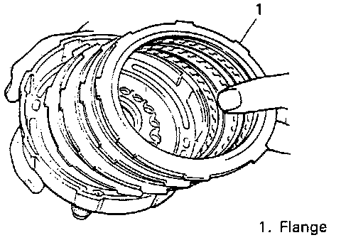
5. Install discs, plates and flange in the following order.
(1) Plate, (2) Disc, (3) Plate, (4) Disc, (5) Plate, (6) Disc, (7) Flange
NOTE: Before assembly, new discs should be soaked in automatic transmission fluid for 2 hours or more.
6. Install clutch plate snap ring.
7. After installing clutch plate snap ring, measure height between snap ring and clutch flange as previously outlined. If discs and plates are new and yet out of specification, install flange of different thickness. Following 2 types of clutch flanges are available as spare parts.
Height "a": 2.01 - 2.68 mm (0.079 - 0.105 inch)
Available clutch flange size (thickness):
3.00 mm (0.118 inch)
3.37 mm (0.132 inch)
8. Check clutch piston for movement by blowing air through input shaft oil hole.
CAUTION: Apply only low pressure air, or spring seat may be damaged.
Valve Body
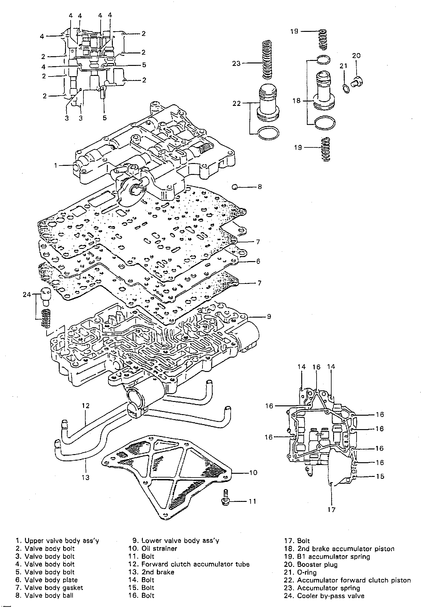
Important Steps in Disassembly and Reassembly of Valve Bodies
- When disassembling valve body, be sure to keep each valve together with its corresponding spring.
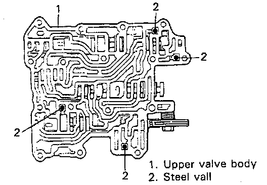
- When removing upper valve body from lower one, be careful not to let 4 steel balls shown in figure fall off.
- When assembling, install these four (4) steel balls in upper valve body as shown in figure.
- Replace each gasket with new one. Make sure that new gasket is the same as the old one before installation.
- When installing each valve to valve body, use special care for proper installing direction.
- Several of the throttle valve rings are used at throttle valve in upper valve body. Be sure to install the same number of throttle valve rings as those used before disassembly.
- When installing lower valve body cover and gasket to lower valve body, tighten lower valve body bolts to specification.
Tightening Torque: 4 - 6 Nm (0.4 - 0.6 kg-m, 3.0 - 4.0 ft. lbs.)
- Tighten throttle valve cam bolt to specification.
Tightening Torque: 6 - 9 Nm (0.6 - 0.9 kg-m, 4.5 - 6.5 ft. lbs.)
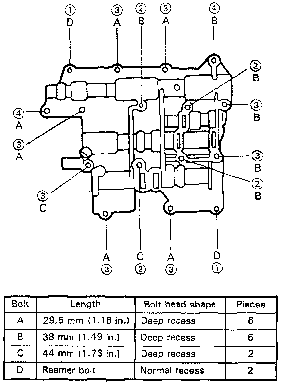
- When installing upper valve body to lower one, install 16 upper valve body bolts and tighten them to specified torque.
1.-Lightly install 2 reamer bolts (positioning bolts) to "D".
2.-Install all other 14 bolts.
3.-Tighten 4 bolts (2) to specification.
4.-Tighten 8 bolts (3) to specification.
5.-Tighten 2 bolts (4) and 2 reamer bolts (1) to specification.
Tightening Torque: 5 - 6 Nm (0.5 - 0.6 kg-m, 4.0 ft. lbs.)
Countershaft And Output Shaft
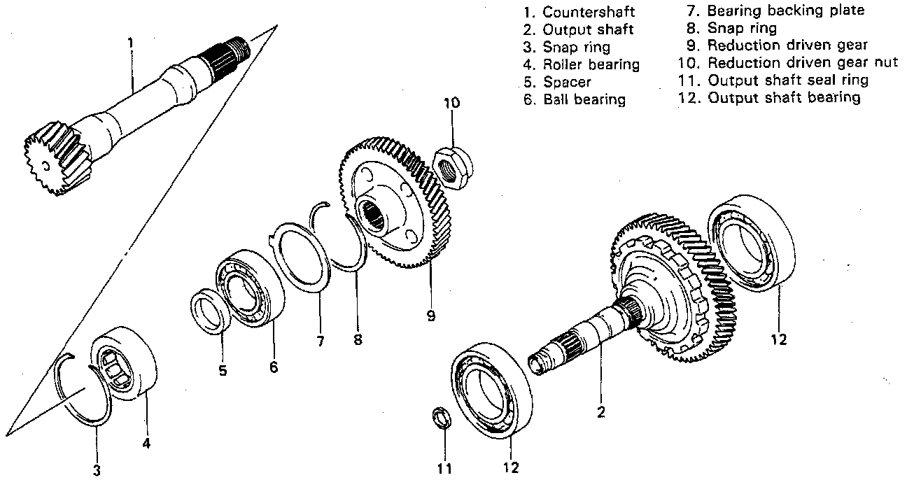
Countershaft Bearings Removal
1. Remove snap rings by using a screwdriver.
2. Remove backing plate (rear cover side).
3. Remove front and rear counter shaft bearings.
(1) Using special tools (Bearing remover and sliding shaft), remove bearing.
(2) Remove other side of bearing in the same way.
Special Tool
(A): 09941 -64511
(B): 09930-30102
Countershaft Bearings Installation
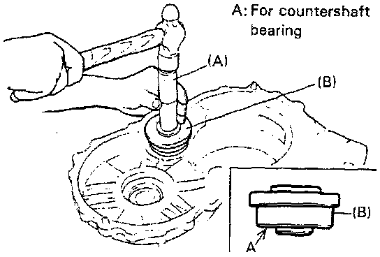
1. Install countershaft bearing (Roller bearing) to case. Use special tools (Bearing installer attachment and installer handle). The bearing installer attachment has two sides. Use small side A for installation of countershaft bearings.
Special Tool
(A): 09924-74510
(B): 09926-88310
2. Install snap ring.
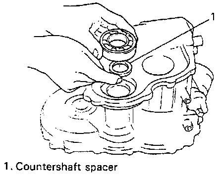
3. Install countershaft spacer to case.
4. Install another countershaft bearing (ball bearing) to case. Use special tools (Bearing installer attachment and installer handle).
5. Install bearing backing plate and snap ring.
Output Shaft Bearings Removal
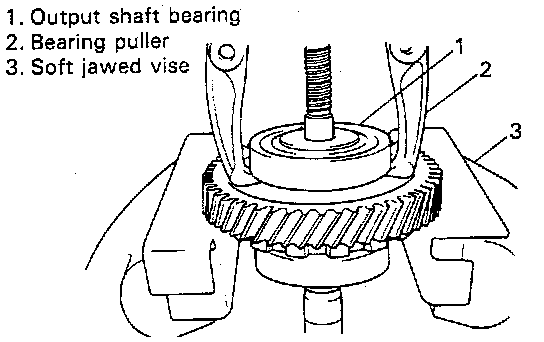
1. Remove cover side bearing. Hold output shaft with soft jawed vise and remove bearing by using bearing puller.
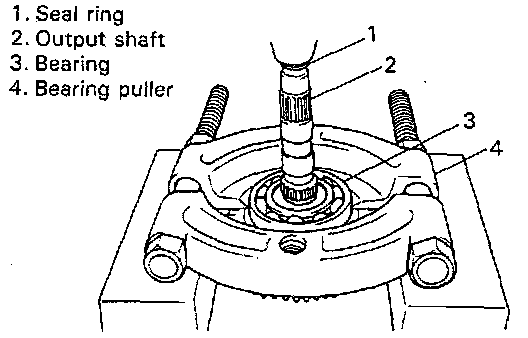
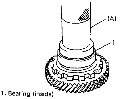
2. Install inside bearing. Hold bearing by using bearing puller and drive out shaft with press.
CAUTION: Never hit shaft end where seal ring is installed so as not to distort ring slit.
Output Shaft Bearings Installation
1. Install inside bearing. Use special tool with press.
Special Tool (A): 09913-85210
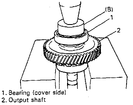
2. Install cover side bearing. Hold shaft at parking lock gear and press-fit bearing by using special tool with press.
Special Tool (B): 09944-66020
Differential Assembly
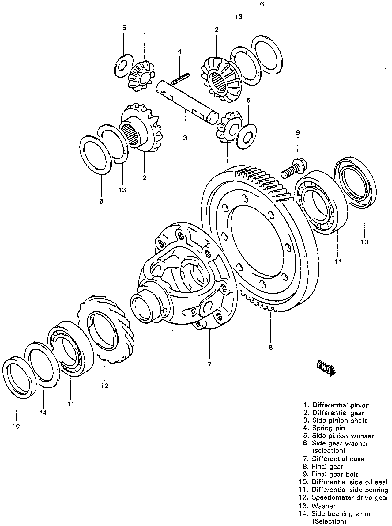
Servicing procedure for differential assembly is similar to that for manual transmission.
Disassembly
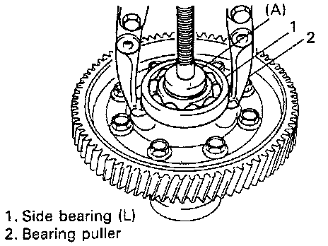
1. Remove differential side bearing (L). Use special tool and puller for its removal.
Special Tool (A): 09925-88210
2. Remove final gear. Hold differential case with soft jawed vise and remove 8 bolts then take out final gear.
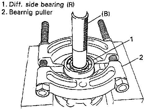
3. Remove differential side bearing (R). Drive it out by using special tool, bearing puller and press.
Special Tool (B): 09913-80112
4. Remove speedometer drive gear.
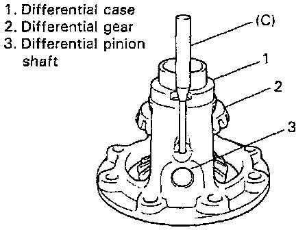
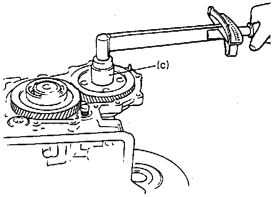
5. Remove side pinion shaft pin. Use special tool and hammer for its removal.
Special Tool (C): 09922-85811
6. Remove side pinion shaft, differential pinions with each washer, differential gears with each washer.
Adjustment And Reassembly
Prepare replacing parts as required and proceed to reassembly. Make sure that all parts are clean.
1. Install differential gears. Measure and adjust thrust play, and then assemble them with suitable thrust washers.
2. Drive in side pinion shaft pin from right side till it is flush with differential case surface.
3. Install differential side bearing (L). Face its seal side inward (differential case side) and press-fit by using the same special tool with right hand bearing in step 5.
4. Install speedometer drive gear.
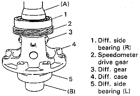
5. Install differential side bearing (R). Face its seal side inward and press-fit it by using special tool with copper hammer. While press-fitting, support differential assembly as illustrated so that left hand bearing is floating.
Special Tool:
(A): 09951-76010
(B): 09951-16060
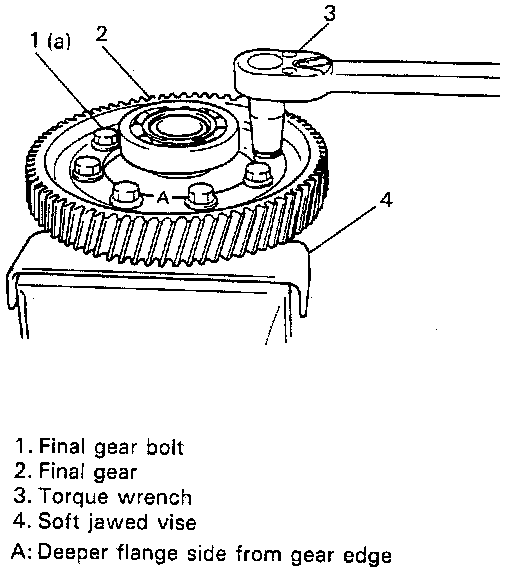
6. Hold differential assembly with soft jawed vise, install final gear and then tighten it with 8 bolts to specified torque.
NOTE: Place offset side of final gear flange toward differential case.
CAUTION: Use of any other bolts than specified ones is prohibited.
Tightening Torque (a): 80 - 90 Nm (8.0 - 9.0 kg-m, 58.0 - 65.0 ft. lbs.)
Shim Adjustment For Differential Side Bearing
Before installing differential assembly to transmission case, select a differential side bearing shim as follows.
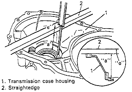
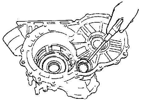
1. With gasket removed, measure dimension "a" of transmission case housing (from mating surface to bearing bore bottom) by using straightedge and vernier caliper. The dimension "a" can be obtained by subtracting straightedge width "d" from measured value.
Dimension "a" = measured value - straightedge width "e"
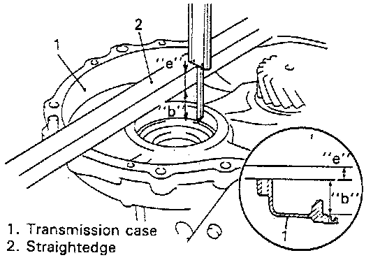
2. In the same manner as the above 1, measure dimension "b" of transmission case (from mating surface to bearing bore bottom).
Dimension "b" = measured value - straightedge width "e"
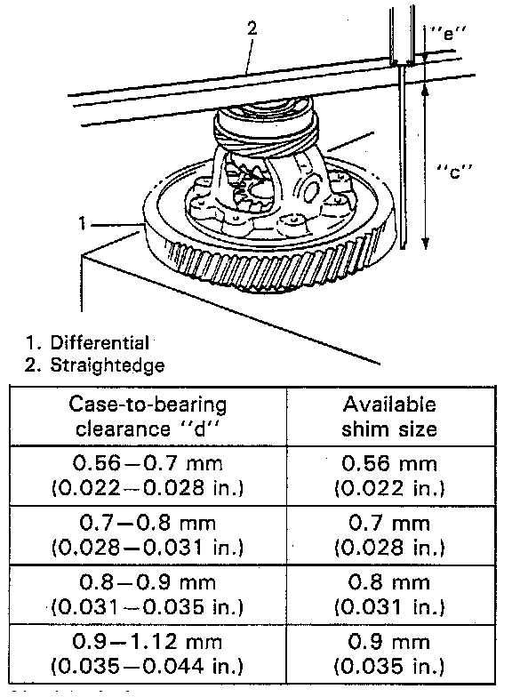
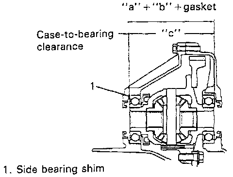
3. Place differential assembly on surface plate and measure dimension "c" (bearing-to-bearing).
Dimension "c" = measured value - straightedge width "d"
4. Obtain case-to-bearing clearance "d" in the following calculation.
"d" = ("a" + "b" + 0.4) - ("c" + 0.2)
Note:
- 0.4 mm (0.016 inch): Gasket thickness
- 0.2 mm (0.008 inch): Intended to absorb the measurement error
5. Select a shim from among available sizes and install it between transmission case and side bearing.
CAUTION: Installing of over sized shim beyond specification may cause tight rotation and consequential bearing damage.
UNIT ASSEMBLY
CAUTION:
^ Automatic transmission consists of highly precise parts. As even a flaw in a small part may cause oil leakage or decrease in function, check each part carefully before installation.
^ Clean all parts with compressed air. Never use wiping cloths or rags.
^ Before assembling new clutch discs and brake band, soak them in automatic transmission fluid for at least 2 hours.
^ Be sure to use new gaskets and O-rings.
^ Lubricate O-rings with automatic transmission fluid.
^ Apply automatic transmission fluid on sliding or rotating surfaces of the parts before assembly.
^ Use yellow petrolatum grease or SUZUKI super grease C to retain parts in place.
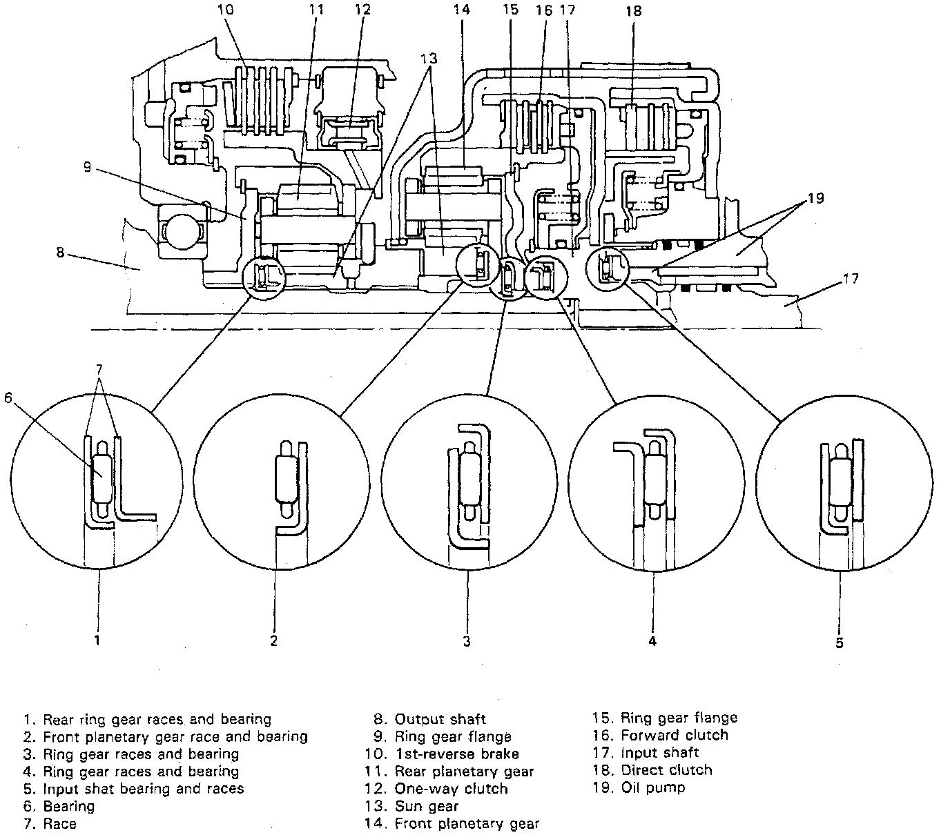
^ Be sure to install thrust bearings and races in correct direction and position as shown in figure.
^ Make sure that snap ring ends are not aligned with one of the cutouts and are installed in groove correctly.
^ Do not use adhesive cements on gaskets and similar parts.
^ Be sure to torque each bolt and nut to specification.
Installation
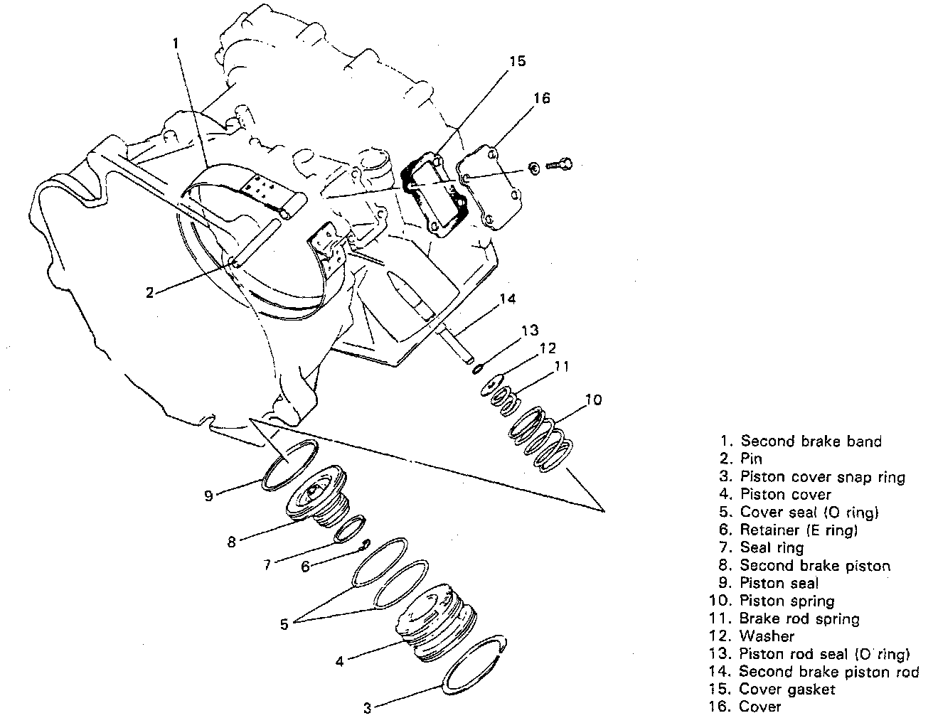
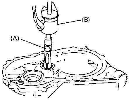
1. Install 2nd brake piston.
(1) Put piston spring in transmission case and insert piston assembly into case after applying fluid to piston rod, seal and seal ring.
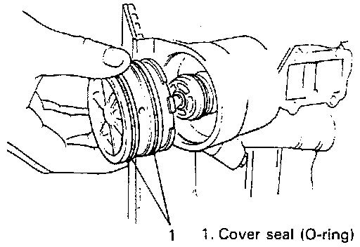
(2) Install piston cover to case after applying fluid to 2 cover seals.
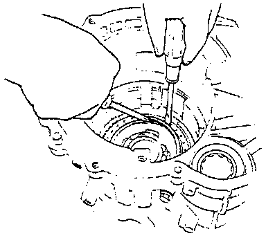
(3) Push down piston cover by using valve lifter with 17 mm socket and install snap ring.
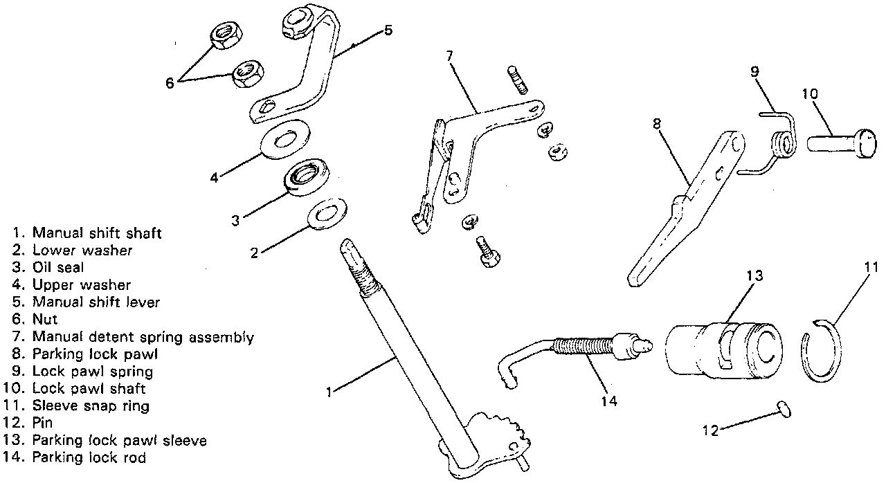
2. Install manual shift shaft and parking lock pawl.
(1) Install lower washer and parking lock rod to manual shift shaft.
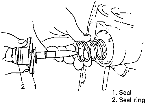
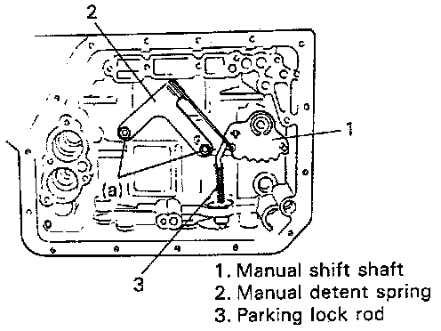
(2) Install manual shift shaft into transmission case, and then, manual detent spring. Use special care so that manual shift shaft will not damage oil seal lip when passing through it.
Tightening Torque (a): 8 - 12 Nm (0.8 - 1.2 kg-m, 6.0 - 8.5 ft. lbs.)
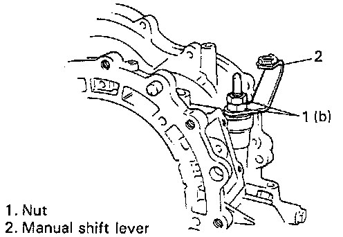
(3) Install shift shaft upper washer and then manual shift lever to manual shift shaft. Tighten lower nut first and then upper nut.
Tightening Torque (b): 27 - 33 Nm (2.7 - 3.3 kg-m, 20.0 - 23.5 ft. lbs.)
(4) After tightening nuts, check manual shift shaft for smooth rotation.
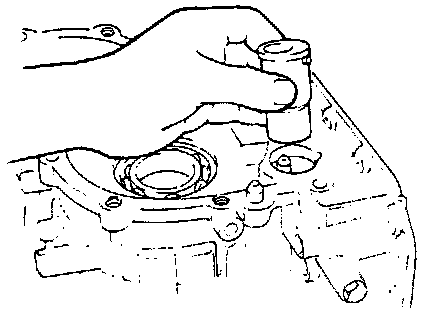
(5) Install restrictor pin and snap ring to parking lock pawl sleeve. And then install it to case.
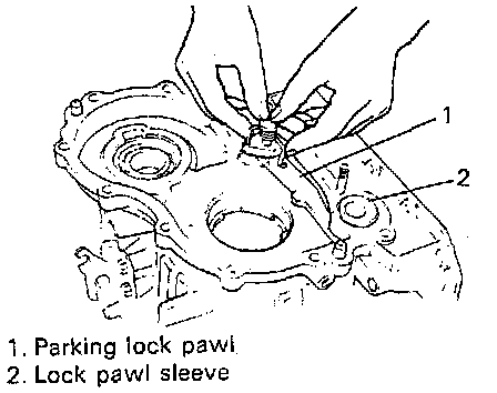
(6) Install parking lock pawl.
a. Shift manual shift lever to a position other than "P".
b. Install parking lock pawl.
c. Install lock pawl shaft and lock pawl spring, and then, check to make sure that parking lock pawl moves smoothly when manual shift lever is moved.
3. Install 1st-reverse brake piston.
(1) Apply fluid to inner and outer seals (O-rings) and fit them to piston. Use new seals.
(2) Insert piston into case in such way that the side with spring holes comes to the top. Make sure that seals are not twisted or caught.
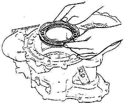
(3) Place return spring assembly on piston. Check to make sure that each spring of return spring assembly is fitted securely in spring hole in piston.
(4) Push down return spring assembly and install snap ring.
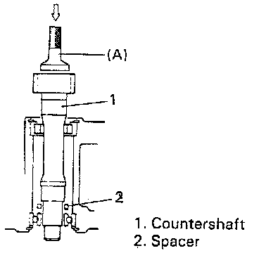
4. Using a special tool (Bearing installer) and a hammer, install countershaft. When inserting countershaft into case, check to make sure that spacer is in such position as shown in figure.
Special Tool (A): 09951-76010
CAUTION: Do not hammer shaft excessively hard, or snap ring and case will be damaged.
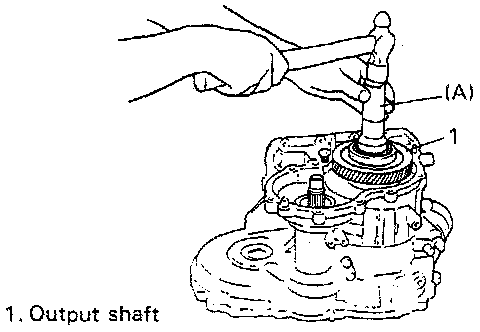
5. Install output shaft.
(1) Shift manual shift lever to a position other than "P".
(2) Using a special tool (Bearing installer) and hammer, install output shaft.
Special Tool (A): 09951-76010
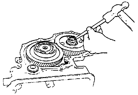
6. Install reduction driven gear on countershaft.
(1) Shift manual shift lever to "P" position so that output shaft is locked and cannot turn.
(2) Tighten driven gear nut to specification.
CAUTION:
^ Tighten nut by turning wrench by hand.
^ Tightening nut by hammering wrench may cause damage to parking lock pawl, output shaft and reduction gear.
Tightening Torque (c): 110 - 150 Nm (11.0 - 15.0 kg-m, 80.0 - 108.0 ft. lbs.)
(3) Using a chisel and a hammer, stake driven gear nut at 2 places.
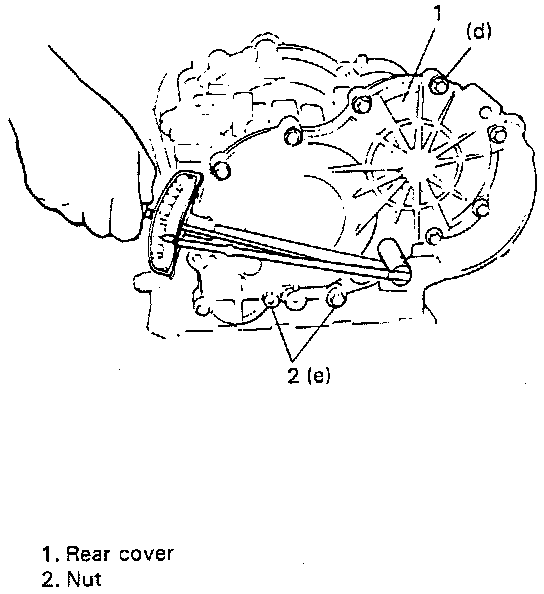
7. Install transmission rear cover.
(1) Install rear cover gasket.
(2) Install rear cover. Check that output shaft bearing enters to rear cover bearing hole smoothly.
(3) Install 10 bolts and 2 nuts. Torque bolts and nuts to following specifications.
NOTE: Check to make sure that the shafts rotate smoothly without abnormal noise.
Tightening Torque
(d): 16 - 23 Nm (1.6 - 2.3 kg-m, 12.0 - 16.5 ft. lbs.)
(e): 11 - 15 Nm (1.1 - 1.5 kg-m, 8.0 - 10.5 ft. lbs.)
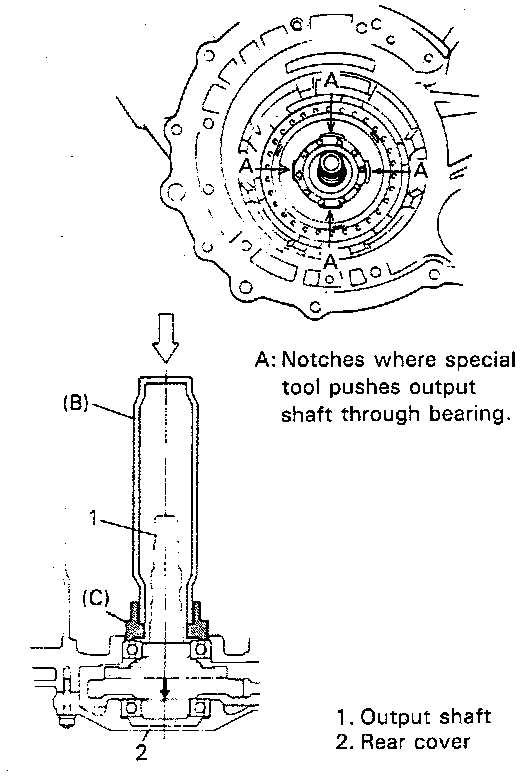
8. Using special tools (Output shaft remover and Bearing remover handle), push output shaft against rear cover side.
(1) Fit 4 projections of special tool (Output shaft remover) to 4 notches A in case.
(2) Push bearing and output shaft against rear cover side by tapping special tool (Bearing remover handle) with a hammer lightly.
Special Tool
- (B): 09925-18010
- (C): 09927-08210
CAUTION:
^ Do not hit output shaft directly, or shaft end will be damaged.
^ Be careful not to hammer with special tool too hard.
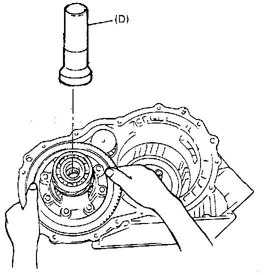
9. After engaging teeth of final gear and countershaft gear, install differential assembly.
CAUTION:
^ Be careful not to damage gear tooth by hitting it with other one.
^ Make sure that differential assembly is placed on case straightly, while installing it.
^ Drive in differential by giving force to side bearing inner race through special tool (bearing installer).
Special Tool (D): 09951-76010
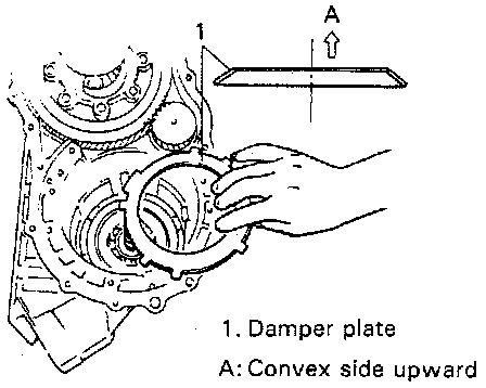
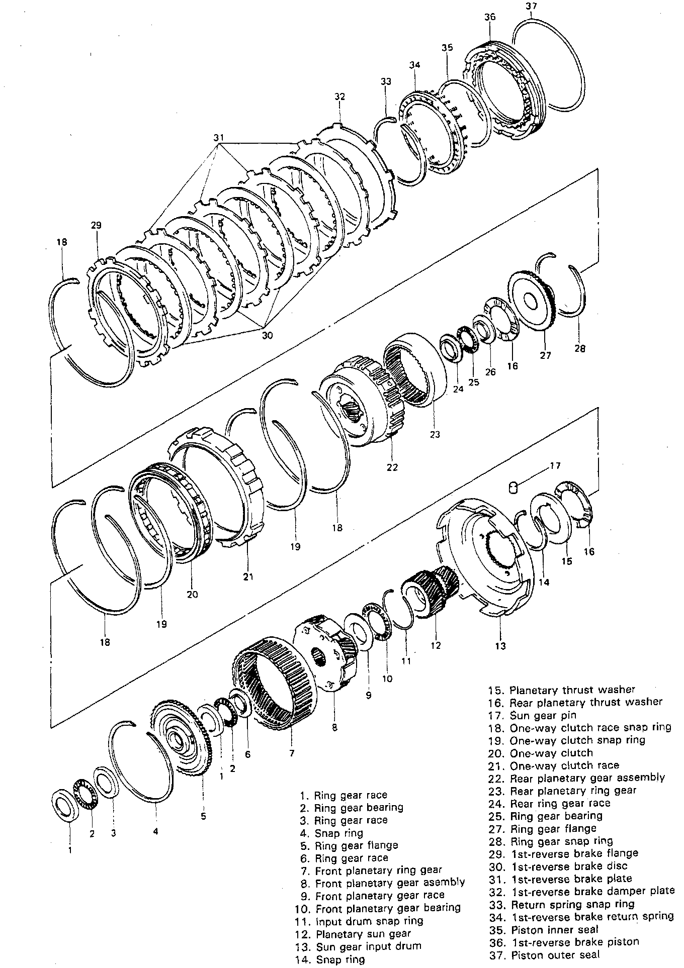
10. Install 1st-reverse brake parts.
(1) Install damper plate to return spring assembly with convex side upward. Use care not to install in reverse direction.
(2) Install discs, plates and flange in following order:
(1) Plate, (2) Disc, (3) Plate, (4) Disc, (5) Plate, (6) Disc, (7) Plate, (8) Disc, (9) Flange (Flat side down)
NOTE: When using new discs for installation, soak them in fluid for more than 2 hours before installation.
(3) Install snap ring.
11. Measure 1st-reverse brake clearance. Measure clearance between snap ring and flange.
1st-reverse brake clearance: 0.58 - 1.92 mm (0.023 - 0.075 inch)
12. Check 1st-reverse brake piston for operation. Check for piston movement by blowing air into oil hole.
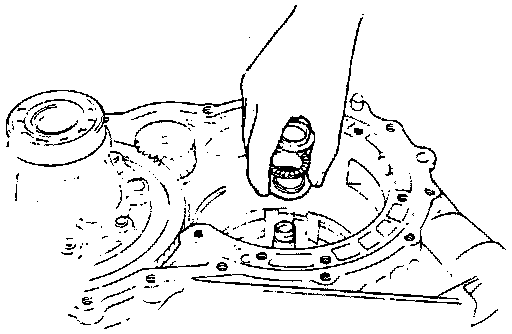
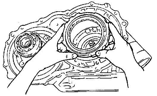
13. Install rear planetary ring gear. Engage ring gear and output shaft spline, and insert.
14. Install rear planetary ring gear races and bearing. Install in the following order:
(1) Race (flange side up)
(2) Bearing
(3) Race (flange side up)
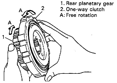
15. Check one-way clutch direction. Provisionally assemble one-way clutch and rear planetary gear, then turn them by hand. They should rotate freely in arrow direction A but lock in the other way. Remove one-way clutch and keep its correct side in mind until it is installed into transmission.
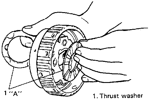
16. Install rear planetary thrust washers on rear planetary gear. Apply grease to thrust washers and fit them before and behind planetary gear, one each. Make sure that different lug shapes match slots in planetary gear.
"A": SUZUKI SUPER GREASE C, 99000-25030
17. Install rear planetary gear with teeth of 1st-reverse brake discs aligned. After installing rear planetary gear, check thrust washers and races for proper installation by moving rear planetary gear up and down lightly by hand. If gear assembly makes clear sound like "Click" when moved up and down, washers and races are installed in place. But if no sound or thick one is heard, it is possible that they are out of place. In such case, remove gear assembly and check.
18. Install one-way clutch race snap ring into groove of transmission case.
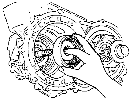
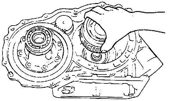
19. Place one-way clutch on rear planetary gear and while turning planetary gear clockwise by hand, insert one-way clutch to correct position.
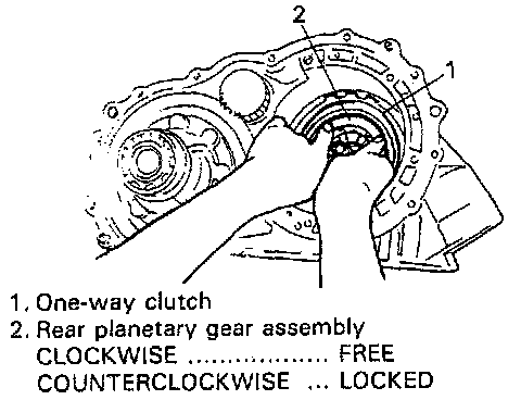
After installing one-way clutch to rear planetary gear, check to confirm that planetary gear turns clockwise but locks in the other way.
NOTE: Rotation check must be performed without fail.