Unit Removal
TRANSMISSION UNIT REMOVAL1. Turn transmission on ATM holder (special tool) so that its oil pan comes to the top and hold it that way.
2. Remove oil pan and its gasket by removing 12 bolts.
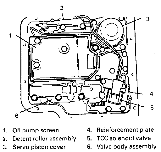
3. Remove detent roller assembly by removing its 2 bolts.
4. Remove oil pump screen (strainer) and gasket by removing its 3 bolts.
5. Remove TCC solenoid valve by removing 2 bolts. Also, remove lead connections then.
NOTE:
^ When removing TCC solenoid valve, use care not to bend its tubes.
^ Also, use care not to lose O-rings for solenoid tubes.
6. Remove reinforcement plate by removing 6 bolts.
7. Remove servo piston cover and gasket by removing 4 bolts.
8. Remove 7 bolts then valve body assembly with manual valve and its link, gasket, transfer plate and gasket.
CAUTION: When removing valve body assembly, be very careful not to let manual valve and its link fall off.
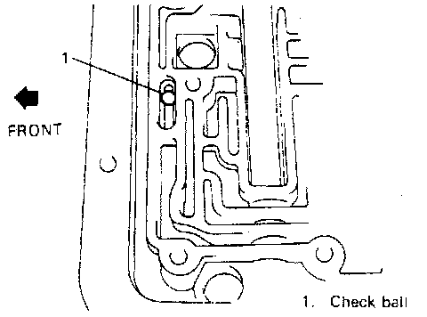
9. Take out check ball and retain it.
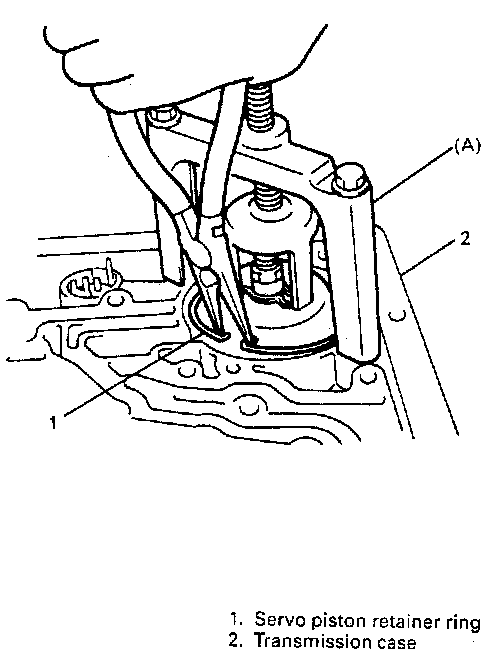
10. With special tool set to transmission case, compress servo piston and then remove servo piston assembly by removing its retainer ring.
NOTE: Before removing special tool from transmission case, be sure to release spring tension of servo piston by loosening compression screw located in the center of special tool.
WARNING: If servo piston retainer ring is removed without compressing piston with special tool, piston will jump out and may cause an injury.
Special Tool
(A): 09927-66020/J-23075
11. Remove servo piston return spring and servo piston rod.
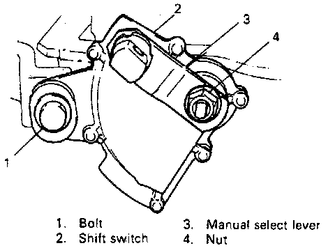
12. Remove manual select lever by removing its fastening nut.
13. Remove shift switch by removing its bolt.
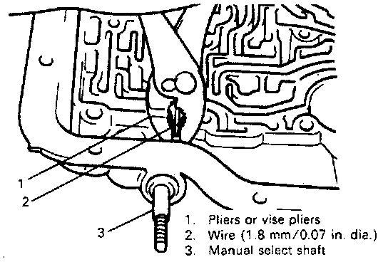
14. With a 1.8 mm (0.07 inch) diameter wire inserted into manual select shaft pin (spring pin), grip that pin by pliers or vise pliers firmly and pull it out.
CAUTION:
^ Be sure to pull spring pin straight out. Applying force to bend it may cause it to break.
^ Attempt to remove spring pin without inserting a wire may result in broken pin.
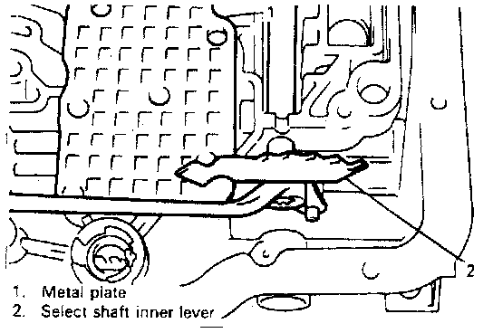
15. With a metal plate placed between manual select shaft inner lever and aluminum transmission case surface to prevent their direct contact, loosen nut at shaft end then remove nut and lever.
CAUTION: Neglecting to place a metal plate between lever and case may, cause case surface to get damaged from its contact with lever.
16. Pull out manual select shaft.
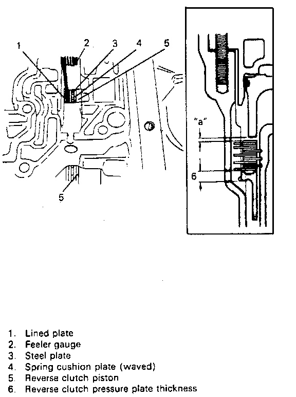
17. Using feeler gauge, measure clearance "a" between reverse clutch plate and reverse clutch piston.
CAUTION: Insert feeler gauge between a lined plate and a steel plate.
Clearance "a": 0.87 - 1.65 mm (0.034 - 0.065 inch)
If clearance is out of specification, check and replace lined plates or steel plates, or select a suitable reverse clutch pressure plate.
18. Using a small screwdriver, take out manual select shaft oil seal.
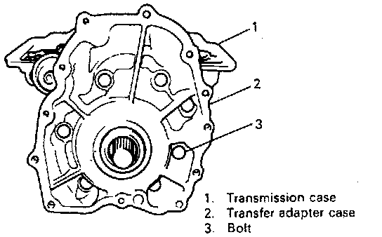
19. Remove transfer adapter case or extension case and gasket by removing 7 fastening bolts.
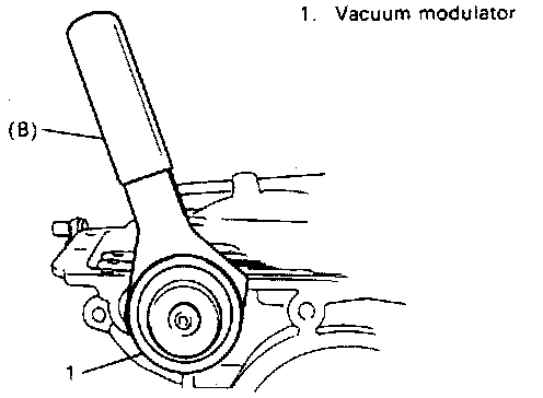
20. Remove clamp bolt and not for vacuum modulator pipe, then disconnect pipe from modulator.
21. Remove modulator with special tool. Then take out modulator plunger.
Special Tool
(B): 09920-36020/J-23100
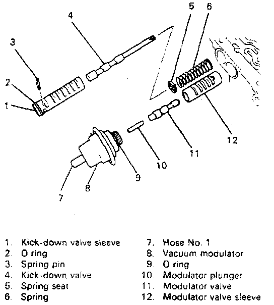
22. With a 1.8 mm (0.07 inch) diameter wire inserted into kick down valve sleeve spring pin, grip that pin tip by pliers or vise pliers securely and pull it straight out.
23. Take out kick-down valve, sleeve, spring seat, spring, modulator valve and sleeve.
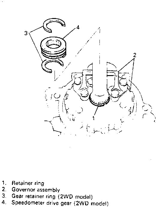
24. Using snap ring opener and small screwdriver, remove retainer ring (circlip) and speedometer drive gear (if equipped), and then remove governor hub and governor body together.
25. Remove governor body from its hub by removing 4 bolts and take out small oil screen.
WARNING: Retainer ring must not be removed from transmission unit in the state as converter housing has been removed. If it is vertical or near vertical, planetary gear carrier etc. in it may fall off and get damaged, which may further cause an injury.
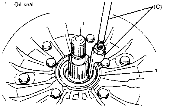
26. If it is necessary to replace oil seal of converter housing, pull it out with special tool.
Special Tool
(c): 09921-96010/J-23129 and J-6125-1B
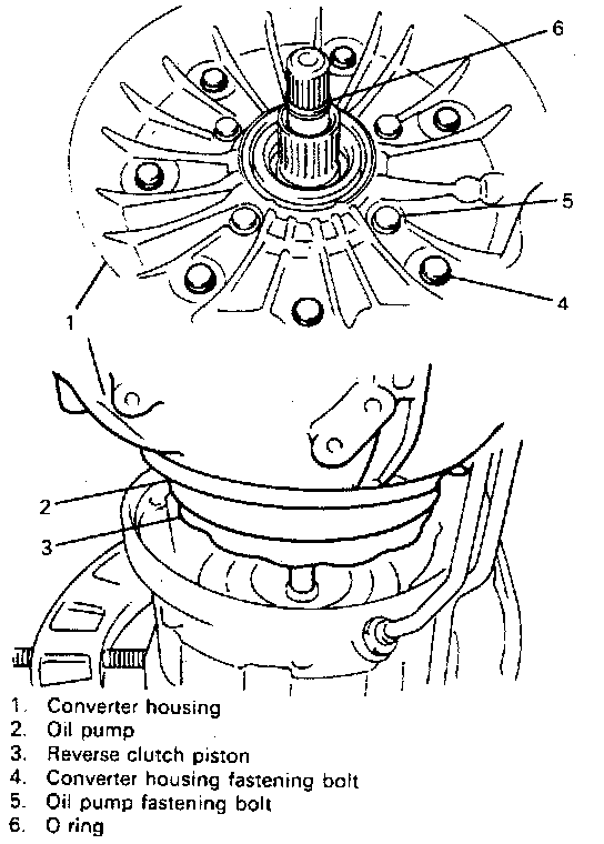
27. Remove O-ring from input shaft.
28. Remove 7 outer bolts in converter housing and remove housing, oil pump and reverse clutch piston assembly all together.
29. Remove gasket between oil pump and transmission case.
NOTE: 5 inner bolts in converter housing for oil pump fastening must not be removed.
WARNING: If converter housing is lifted without removing O-ring, 2nd clutch and 3rd clutch will accompany. Should O-ring be broken in such state, these clutches would drop and get damaged, which further could cause an injury.
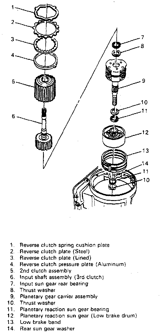
30. Take out 2nd clutch and 3rd clutch assemblies from transmission case by lifting input shaft. Reverse clutch plates are also taken out.
31. Remove remaining reverse clutch plate (steel) and reverse clutch pressure plate (aluminum).
32. Take out planetary gear carrier assembly with thrust, washers and thrust bearings on its upper and lower sides. Only, thrust bearing on the lower (rear) side may remain on planetary reaction sun gear (low brake drum).
33. If thrust bearing has remained on planetary rear sun gear, take it out first and then planetary rear sun gear assembly.
34. Take out low brake band, thrust bearing and thrust washer at the bottom.
35. Take out manual select shaft inner lever and parking lock actuator assembly (rod) together.
36. Separate 2nd clutch and 3rd clutch.
37. Pull out electrical connector from case by pushing 3 claws inward.
38. Remove transmission case baffle plate.