Electronic Shift Control
ELECTRONIC SHIFT CONTROL SYSTEM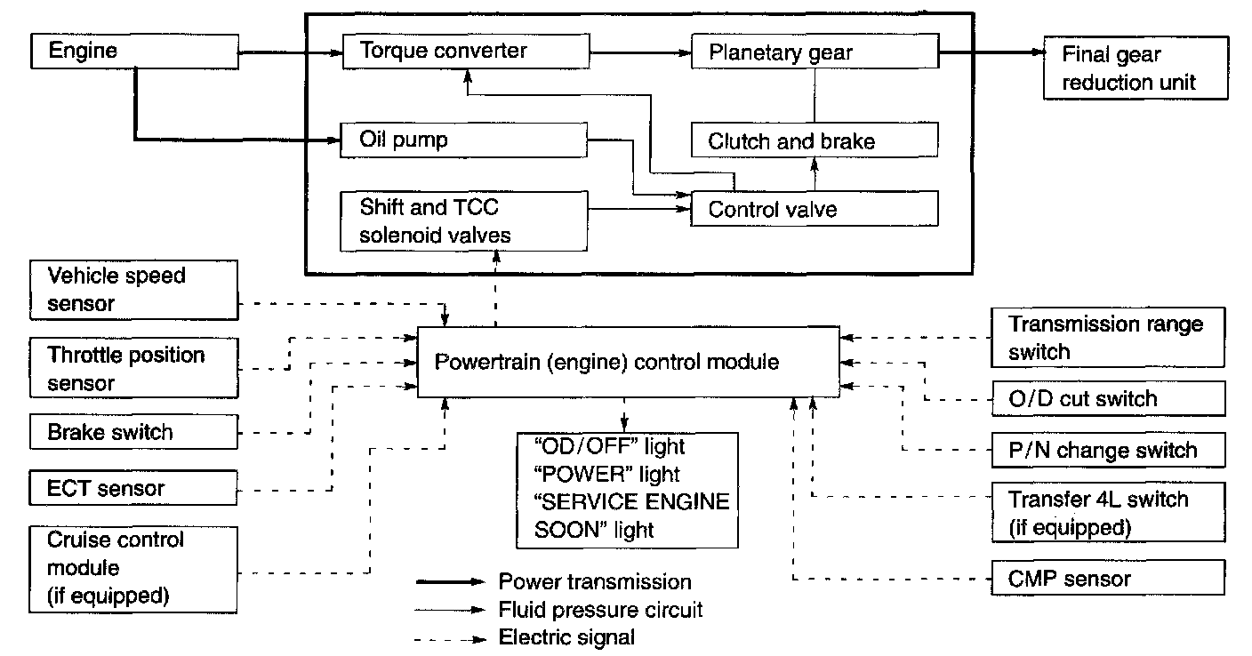
The gear ratio change in "D" or "2" range and torque converter clutch operation are controlled by Powertrain (Engine) Control Module.
Power (Engine) Control Module (PCM, ECM)
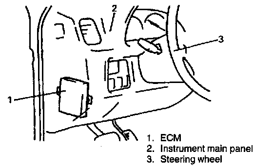
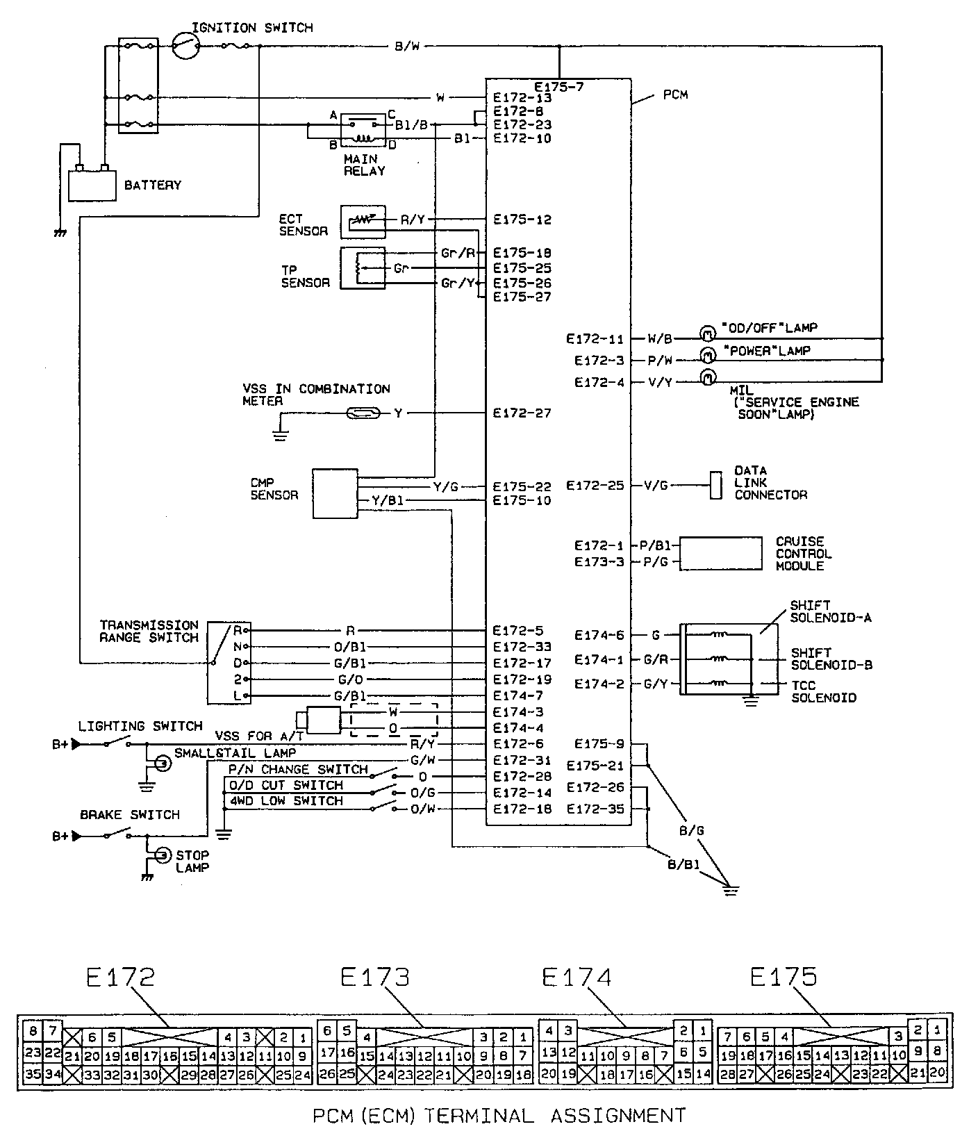
The PCM (ECM) controls not only engine & emission devises but also gear shift and torque converter clutch (shift and torque converter clutch solenoids) according to the signal from each sensor.
Throttle Position Sensor
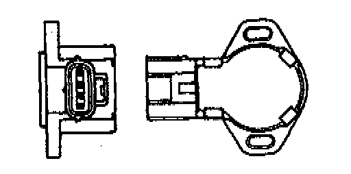
This sensor is installed to the throttle valve shaft. Throttle valve opening signals are transmitted from TP sensor to PCM (ECM) as voltage signal.
Vehicle Speed Sensor
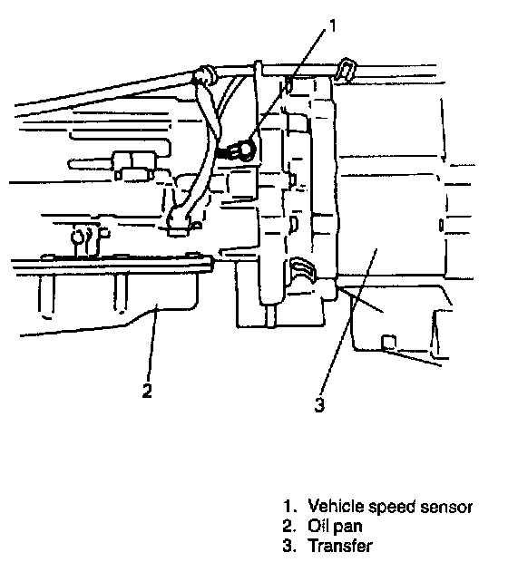
This sensor is a pulse generator type that detects revolution of the output shaft (vehicle speed) in the transmission case. The pulse generator is a noncontact sensor consisting of a permanent magnet, coil and gears. As the gear of the output shaft turns, the magneflux from the permanent magnet varies and a voltage of the frequency corresponding to the rotor revolution occurs in the coil. This voltage is inputted to the PCM (ECM) where PCM (ECM) judges the output shaft revolution or the vehicle speed. The vehicle speed is also detected from the speed meter
Transmission Range Switch
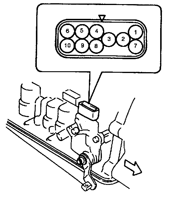
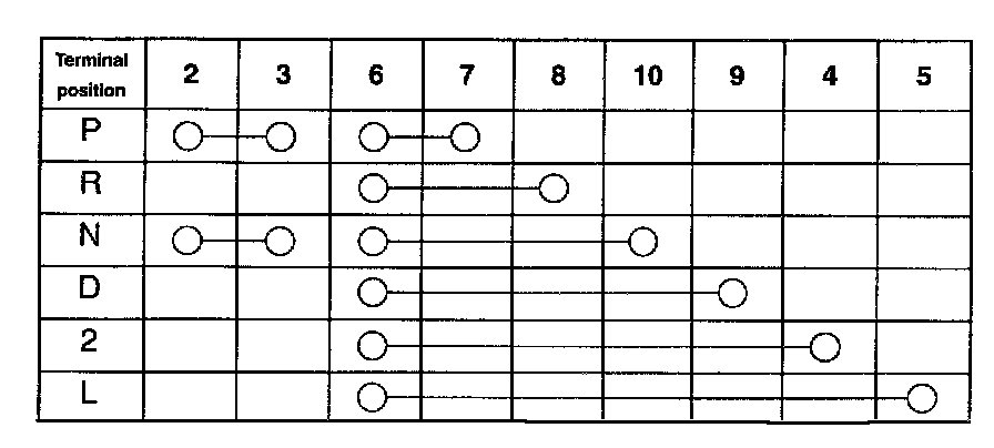
The transmission range switch sends selector lever position to PCM (ECM) as a voltage signal. Also, it is provided so that the engine can be started only when the shift lever is in the "P" or "N" position.
Brake Switch
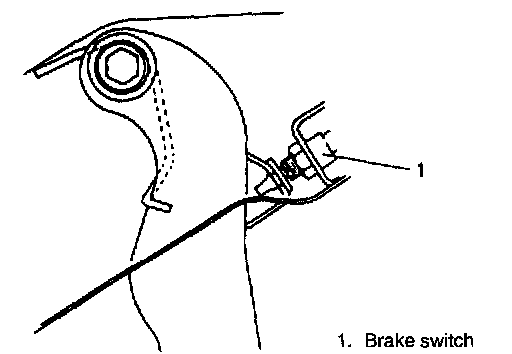
The same switch is used as the brake lamp switch. It disengages the torque converter (lock-up) clutch when the brake is depressed while the torque converter (lock-up) clutch is operating.
Engine Coolant Temperature Sensor (ECT Sensor)
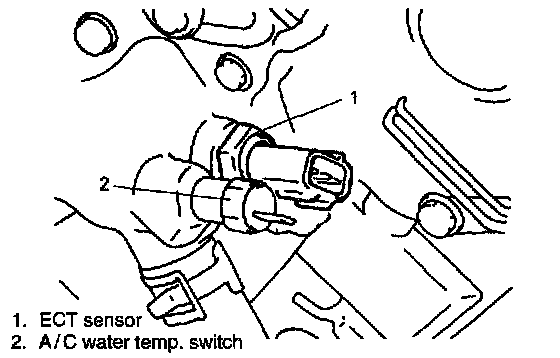
The coolant temperature sensor of the engine & emission control system is used and it prevents gear change to the O/D gear and lock-up when the engine coolant temperature is 30°C (86°F) or lower.
Cruise Control Module (if equipped)
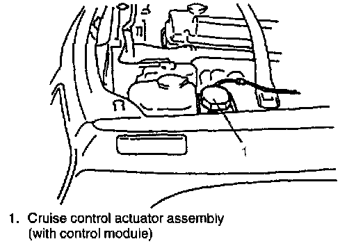
The cruise control module including the cruise control actuator assembly sends an overdrive cut signal to the PCM (ECM). The PCM uses it as one of the signals to control the gear shift up or shift down to and from the O/D gear and torque converter clutch.
Overdrive (O/D) Cut Switch
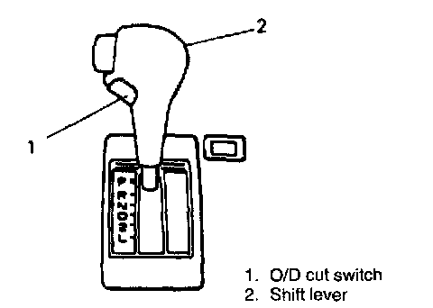
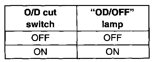
The gear shift up or shift down to and from the O/D gear can be selected with this switch.
Transfer 4L Switch (4WD Model)
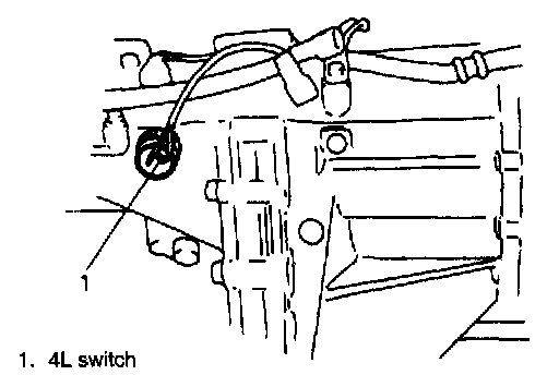
This switch detects that the 4-wheel drive low gear is engaged and prevents the gear change into O/D and lock-up.
P/N Change Switch
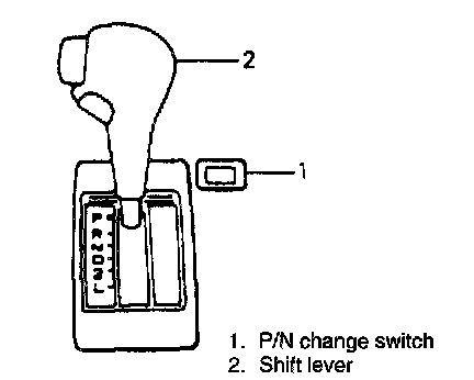
The gear shift timing, normal or power, can be selected by using this switch.
Camshaft Position Sensor (CMP sensor)
The camshaft position sensor sends the pulse signal to the PCM (ECM). By using this signal the PCM knows the engine speed and detects the actual transmission gear ratio (input/output ratio).
Fail Safe Function
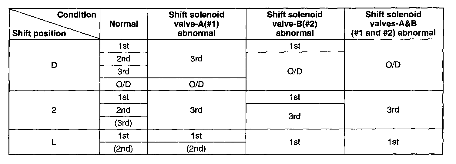
This function is provided by the safe mechanism that assures safe driveability even when the shift solenoid valve or speed sensor fails. The table shows the gear position in each shift under a normal/abnormal condition.
Change Mechanism

The same select pattern shift lever is used as the floor type and frequently used "N" and "D" ranges are made selectable freely.
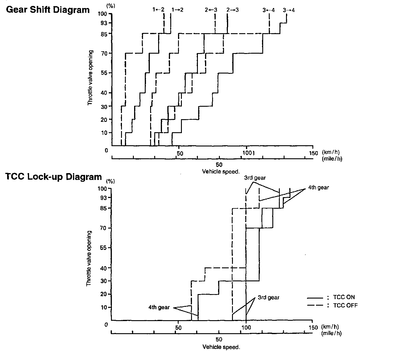
AUTOMATIC GEAR SHIFT DIAGRAM
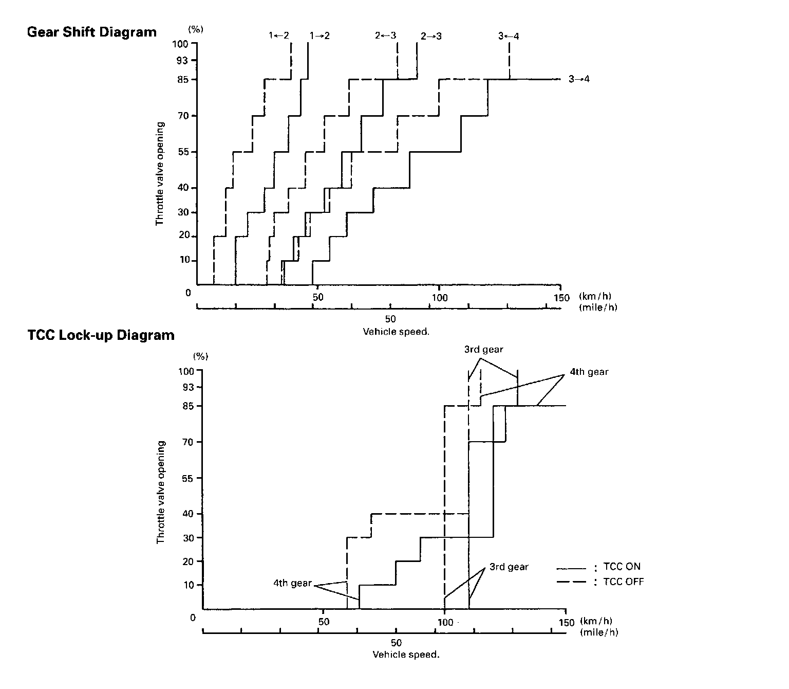
Power Mode
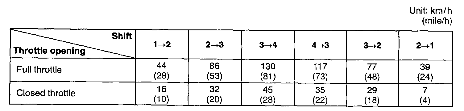
Normal Mode
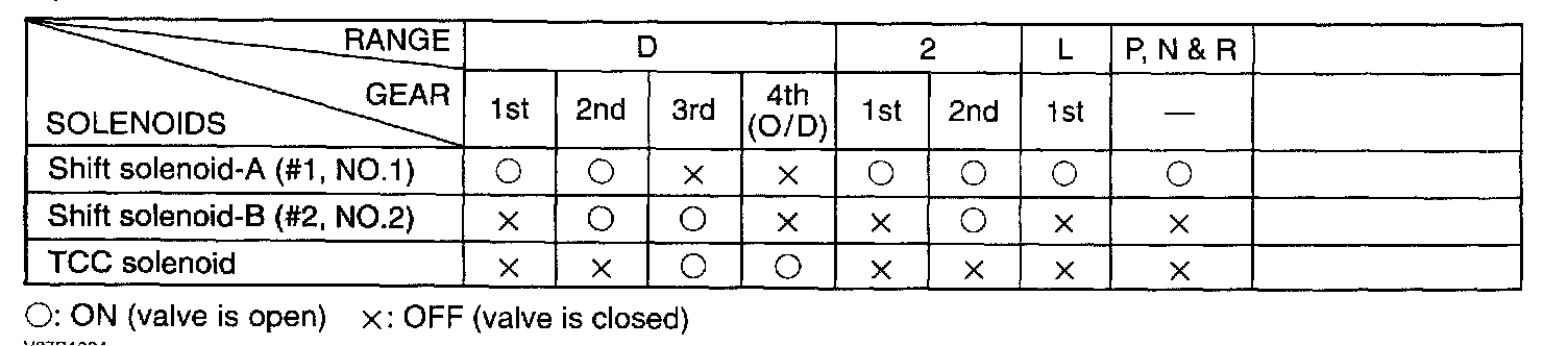
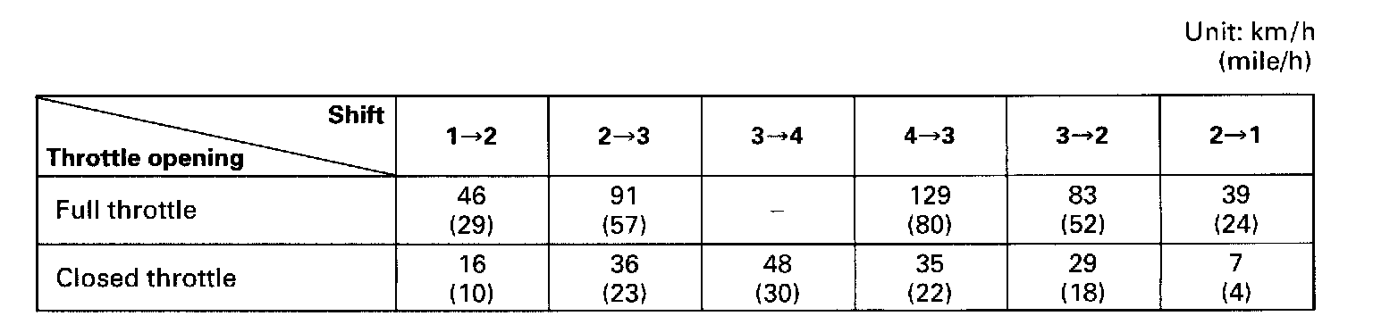
Operation of Shift Solenoids and TCC Solenoid
Automatic shift schedule as a result of shift control as shown. In case that select lever is shifted to L at a higher than 52 km/h (32.5 mile/h) speed, 2nd gear is operated and then down shifts to 1st at a speed lower than that. No upshift is available in L.
The same as, the select lever is shifted to 2 at a higher than 100 km/h (62.5 mile/h) speed, 3rd gear is operated and then down shifts to 2nd at a speed lower than that. No up shift is available in 2.