P0500
DTC P0500 VEHICLE SPEED SENSOR MALFUNCTION
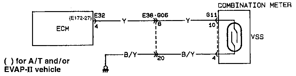
WIRING DIAGRAM
CIRCUIT DESCRIPTION
The speed sensor consisting of the reed switch and magnet is built in the speedometer. As the magnet turns with the speedometer cable, its magnetic force causes the reed switch to turn ON and OFF. Such ON/OFF frequency increases or decreases in proportion with the vehicle speed and is sent to ECM as pulse signals.
ECM uses it as one of the signals to control various devices.
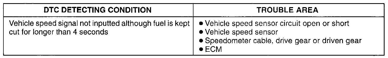
DETECTING CONDITION
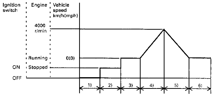
DTC CONFIRMATION PROCEDURE
WARNING:
- When performing a road test, select a place where there is no traffic or possibility of a traffic accident and be very careful during testing to avoid occurrence of an accident.
- Road test should be carried out with 2 persons, a driver and a tester, on a level road.
NOTE: Check to make sure that following conditions are satisfied when using this DTC CONFIRMATION PROCEDURE.
- Intake air temp.: -14°C, 6.8°F or higher.
- Barometric pressure (Altitude) : 540 mmHg, 72 kPa or more (2790m, 9150 ft or less).
1) Connect scan tool to DLC with ignition switch OFF.
2) Turn ON ignition switch and clear DTC, pending DTC and freeze frame data by using scan tool.
3) Start engine and warm up it completely.
4) Increase vehicle speed till engine speed is reached 4,000 r/min in 3rd gear (M/T) or 2 range (A/T).
5) Release accelerator pedal and with engine brake applied, keep vehicle coasting and then stop vehicle.
6) Check DTC by using scan tool.
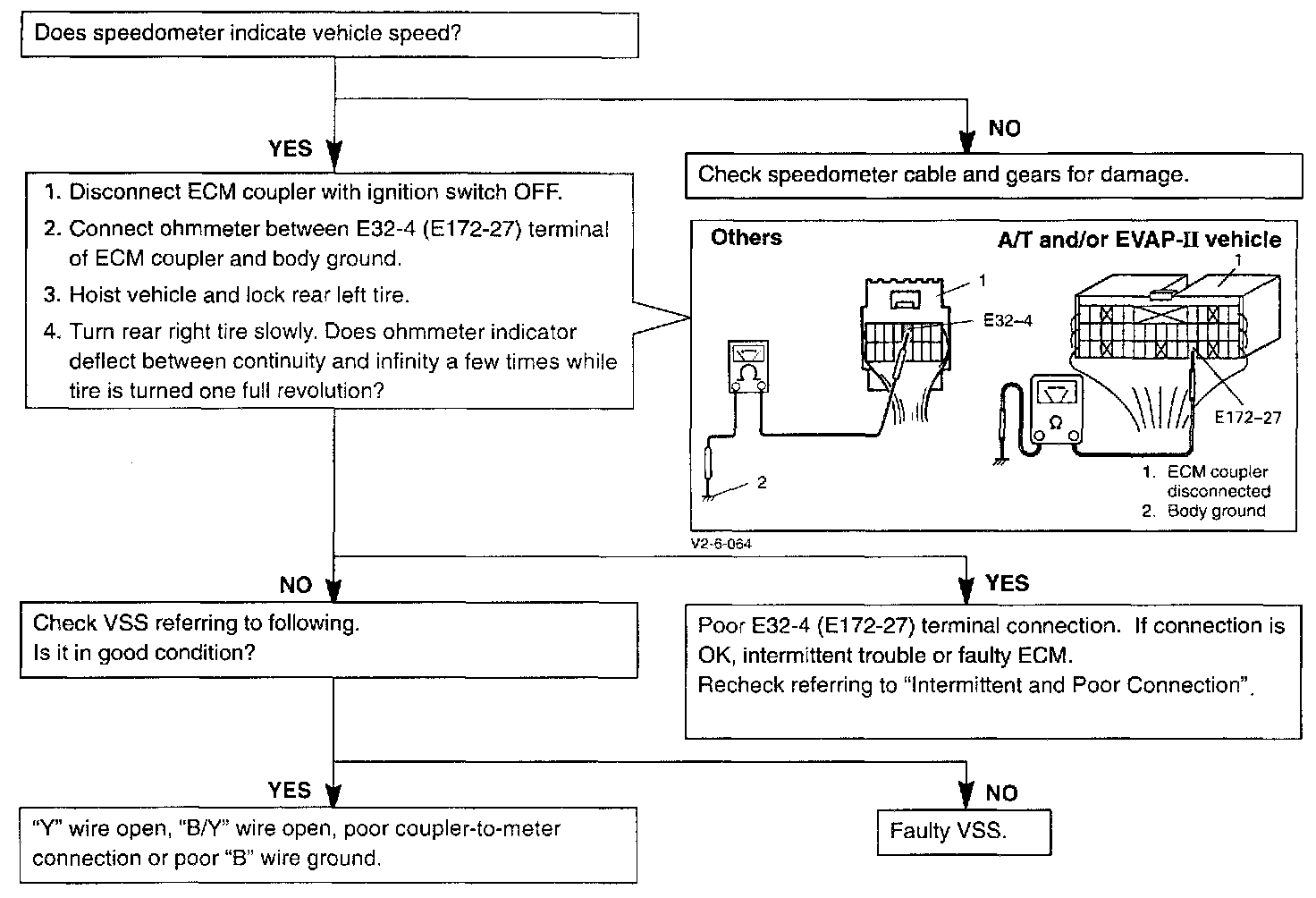
TROUBLESHOOTING
VEHICLE SPEED SENSOR (VSS)
Inspection
1) Disconnect negative cable at battery.
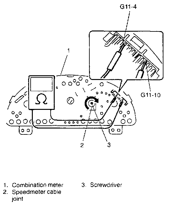
2) Remove combination meter from instrument panel.
3) Connect ohmmeter between G11-4 and G11-1D terminal of combination meter and turn cable joint of speedometer with a screwdriver.
Ohmmeter indicator should move back and forth between 0 (zero) and 00 (infinity) 4 times while cable joint is turned one full revolution.
Replace speedometer if check result is not satisfactory.
4) Install combination meter to instrument panel.
5) Connect negative cable to battery.