Step 6
Tank Pressure Control Solenoid Vacuum Valve, Its Circuit and Vacuum Passage Inspection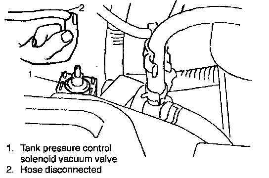
1) Disconnect vacuum hose from tank pressure control solenoid vacuum valve.
2) Start engine and run it at idle speed.
3) With finger placed against disconnected vacuum hose, check that vacuum it applied.
If it is not applied, clean vacuum passage by blowing compressed air or replace vacuum hose.
Using SUZUKI scan tool
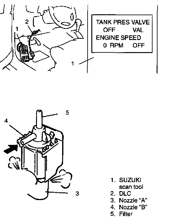
4) Connect SUZUKI scan tool to DLC with ignition switch OFF.
4a) Turn OFF tank pressure control solenoid vacuum valve by using SUZUKI scan tool with ignition switch ON after clearing DTC.
In this state, blow nozzle "A".
Air should come out of filter and not out of nozzle "B".
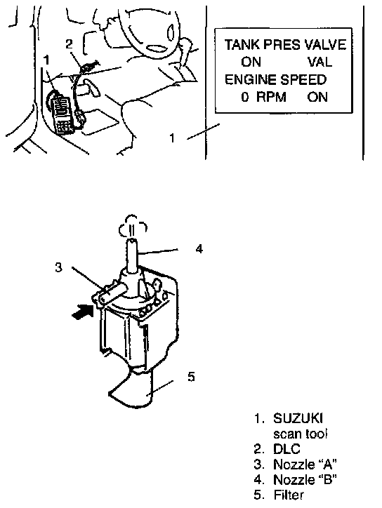
4b) Turn ON tank pressure control solenoid vacuum valve by using SUZUKI scan tool with ignition switch ON.
In this state, blow nozzle "A".
Air should come out of nozzle "B" and not out of filter.
If check results are as described above, tank pressure control solenoid vacuum valve and its circuit are in good condition, connect vacuum hoses securely.
If not, proceed to step 5).
Not using SUZUKI scan tool
4) Turn ON ignition switch but engine stops. In this state, blow nozzle "A".
Air should come out of filter and not out of nozzle "B".
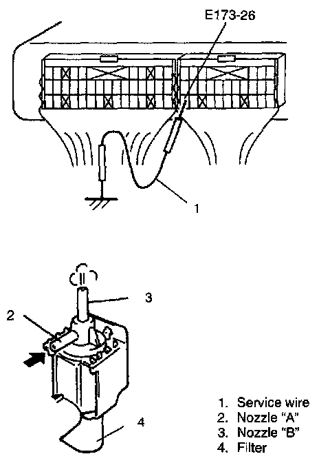
4a) By using service wire, connect E173-26 terminal of ECM coupler and body ground with ignition switch OFF.
4b) Turn ON ignition switch. In this state, blow nozzle "A".
Air should come out of nozzle "B" and not out of filter.
If check results are as described above and E173-26 terminal and ECM connection is OK, tank pressure control solenoid vacuum valve and its circuit are in good condition, connect vacuum hoses securely.
If not, proceed to step 5).
5) With ignition switch OFF, disconnect coupler from valve.
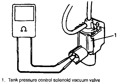
6) Check resistance between two terminals of tank pressure control solenoid vacuum valve.
Resistance of tank pressure control solenoid vacuum valve: 28-36ohms at 20°C (68°F)
If resistance is as specified, proceed to next operation. If not, replace.
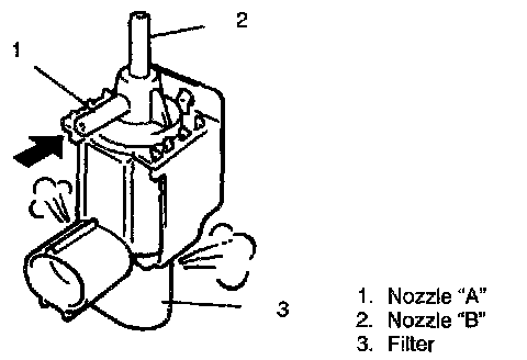
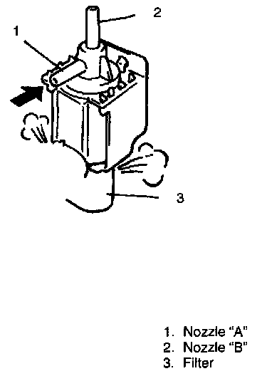
7) With coupler disconnected, blow into nozzle "A". Air should come out of filter and not out of nozzle "B".
If not, replace tank pressure control solenoid vacuum valve.
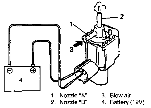
8) Connect 12V-battery to tank pressure control solenoid vacuum valve terminals.
In this state, blow into nozzle "A".
Air should come out of nozzle "B" and not out of filter. If check result is as specified above, check tank pressure control solenoid vacuum valve harness and connectors.
If not, replace tank pressure control solenoid vacuum valve.
9) Connect vacuum hoses.
10) Connect tank pressure control solenoid vacuum valve coupler securely.