P0400
DTC P0400 EXHAUST GAS RECIRCULATION FLOW MALFUNCTION
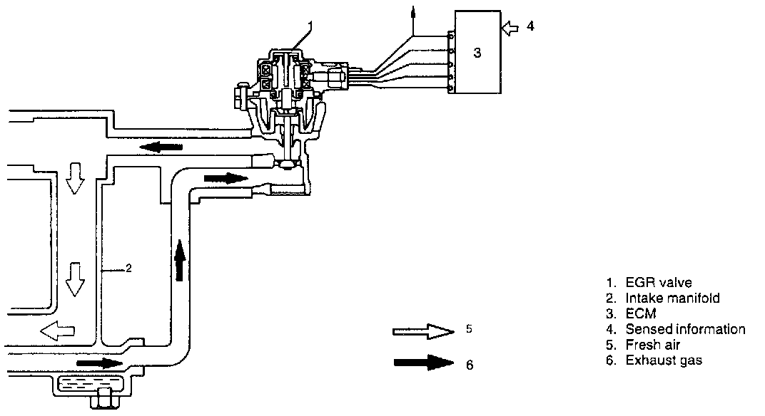
SYSTEM DIAGRAM
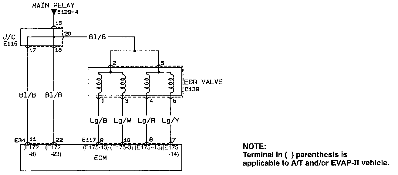
WIRING DIAGRAM
CIRCUIT DESCRIPTION
This system controls the formation of NOx emission by recirculating the exhaust gas into the combustion chamber through the intake manifold.
The EGR system consists EGR valve and piping for exhaust gas.
The EGR valve is controlled by ECM according to the signals from CMP sensor, ECT sensor, MAF sensor and VSS.
The EGR valve consists of a stepper motor, rods, valve, etc.
When the EGR valve stepper motor receives "open" signal from ECM, it turns in the "open" direction according to the number of steps and pushes out the rod which is in mesh with the worm of the stepper motor. As the rod installed to the EGR valve is pushed by this rod, the EGR valve opens by the amount corresponding to the number of steps of the "open" signal from ECM to let the exhaust gas flow from the exhaust manifold to the intake manifold.
To close the EGR valve, the stepper motor turns in the "close" direction according to the number of steps of the "close" signal from ECM and pulls up the rod. In this way, the valve is closed by the spring force.
And in this state, the exhaust gas is not allowed to flow to the air intake system or the combustion chamber.
Under any one of the following conditions, ECM closes the EGR valve.
- When engine coolant temperature is low
- When throttle valve opening is less than specification.
- When engine is running under high load
- When vehicle is stopped.
Also, in order to check the EGR passage and its valve for clogging, ECM opens the EGR valve to the specified opening while the EGR system is operating and then closes it.
ECM checks variation in the manifold pressure at this time to check whether the EGR passage or valve is clogged.
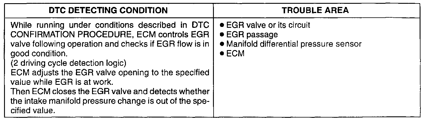
DETECTING CONDITION
DTC CONFIRMATION PROCEDURE
WARNING:
- When performing a road test, select a place where there is no traffic or possibility of a traffic accident and be very careful during testing to avoid occurrence of an accident.
- Road test should be carried out with 2 persons, a driver and a tester, on a level road.
NOTE: Check to make sure that following conditions are satisfied when using this DTC CONFIRMATION PROCEDURE.
- Intake air temp.: between -10°C and 70°C (14°F and 158°F).
- Atmospheric pressure (Altitude) : 540 mmHg, 72 kPa or more (2790m, 9150 ft or less).
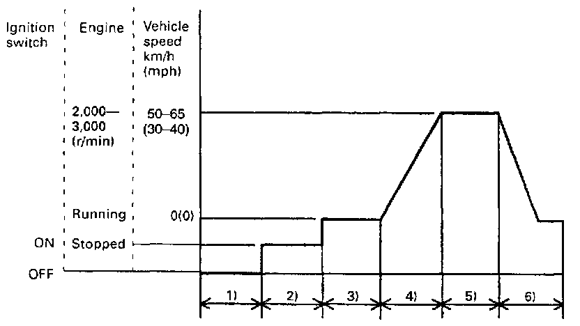
1) Connect scan tool to DLC with ignition switch OFF.
2) Turn ON ignition switch and clear DTC, pending DTC and freeze frame data by using scan tool.
3) Start engine and warm up it completely.
4) Increase vehicle speed to 50 - 65 km/h (30 - 40 mph)(engine speed: 2,000 - 3,000 r/min).
5) keep driving above vehicle speed for 3 min or more (Throttle valve opening is kept constant in this step).
6) Release accelerator pedal, stop vehicle and check pending DTC and DTC by using scan tool.
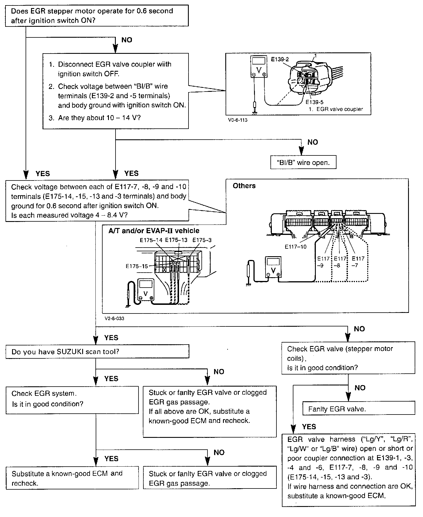
TROUBLESHOOTING