DTC P0135: Heated Oxygen Sensor (Ho2S) No. 1 Heater Circuit Malfunction
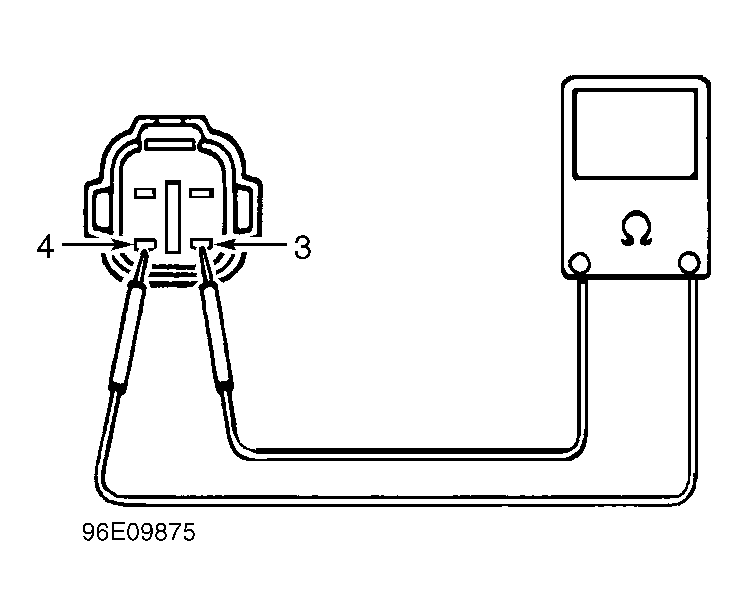
- Disconnect HO2S No. 1 harness connector. Using DVOM, measure resistance between terminals No. 3 and 4 of HO2S No. 1. See Fig 1
. If resistance is 11.7-14.3 ohms, go to next step. If resistance is not as specified, replace HO2S No. 1 and retest system.
 Courtesy of SUZUKI OF AMERICA CORP.
- Reconnect HO2S No. 1 harness connector. Turn ignition on. On models equipped with 3-speed automatic or manual transmission, measure voltage (backprobe) between ground and terminal No. 23 (Pink wire) at 26-pin PCM harness connector. On models equipped with 4-speed automatic transmission, measure voltage (backprobe) between ground and terminal No. 19 (Pink wire) at 26-pin PCM harness connector. If voltage is 10-14 volts, go to next step. If voltage is not as specified, check Black/White wire or Pink wire for an open, Pink wire for a short to ground, or poor HO2S No. 1 harness connection. Repair as necessary. If wires are okay, replace PCM and retest system.
- Start engine and allow it to reach normal operating temperature. On models equipped with 3-speed automatic or manual transmission, measure voltage (backprobe) between ground and terminal No. 23 (Pink wire) at 26-pin PCM harness connector. On models equipped with 4-speed automatic transmission, measure voltage (backprobe) between ground and terminal No. 19 (Pink wire) at 26-pin PCM harness connector. If voltage is 0-1 volt, check for an intermittent problem. See TESTS W/O CODES article. If voltage is not as specified, check for poor PCM harness connection. If connection is okay, replace PCM and retest system.