Hydraulic Control Assembly - Antilock Brakes: Testing and Inspection
OPERATION CHECK1. Check that basic brake system other than Antilock Brake System (ABS) is in good condition.
2. Check that battery voltage is 11V or higher.
3. With "ABS" warning lamp, check that no abnormality is detected in ABS.
4. Lift up vehicle.
5. Set transmission to neutral and release parking brake.
6. Turn each wheel gradually by hand to check if brake dragging occurs. If it does, correct.
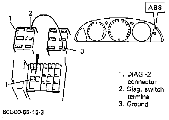
7. With diagnostic switch terminal of DIAGNOSTIC-2 connector connected to ground by using service wire, turn ignition switch ON and check if "ABS" warning lamp indicates DTC 12.
8. Turn ignition switch "OFF".
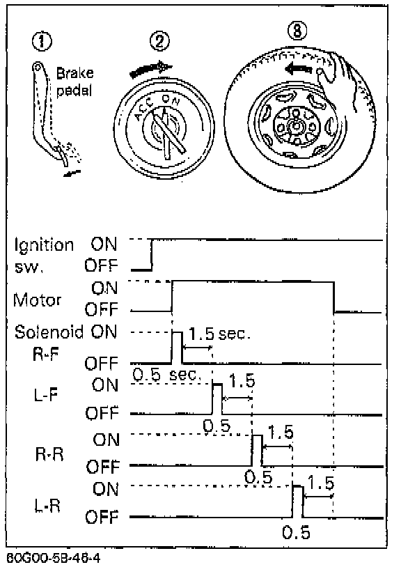
9. Perform following checks with help of another person. Brake pedal should be depressed and then ignition switch turned ON by one person and wheel should be turned by another person's hand. At this time, check that:
^ Operation sound of solenoid is heard and wheel turns only about 0.5 seconds (Brake force is Repressurized).
^ Operation sound of pump motor is heard and pulsation is felt at brake pedal.
10. If all 4-wheels cannot be checked during one ignition cycle OFF-ON), repeat Step 8 and 9 till all 4 wheels are checked. If a faulty condition is found in Steps 9 and 10, replace hydraulic unit.
11. Turn ignition switch "OFF" and remove service wire from DIAGNOSTIC-2 connector.
VISUAL INSPECTION
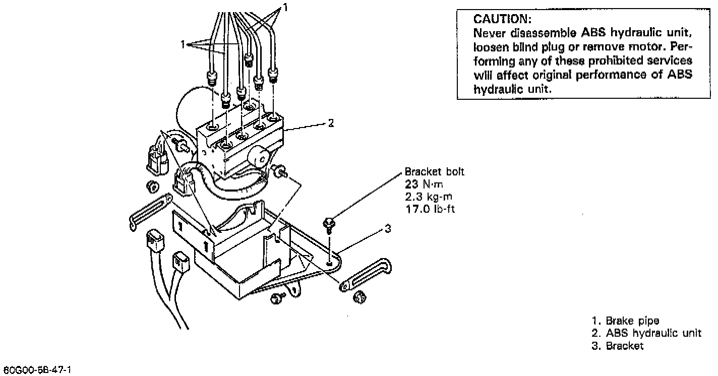
Check hydraulic unit for fluid leakage. If any, repair or replace.
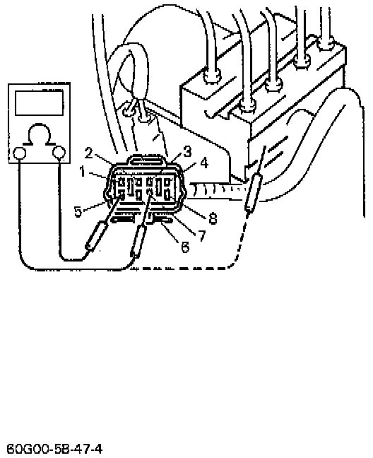
SOLENOID VALVE INSPECTION
1. Turn ignition switch "OFF".
2. Disconnect solenoid connector.
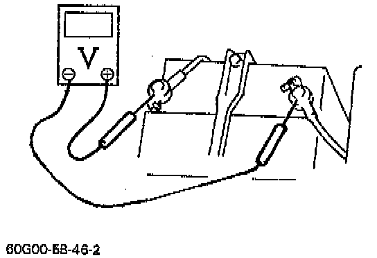
3. Check resistance between terminals and whether or not short-circuit between each terminal and hydraulic unit body exists. Between terminals: 1 and 3, 2 and 4, 5 and 7 & 6 and 8 should be 2.9-3.2 ohms at 20�C (68�F). Between each terminal and unit body should be infinite. If faulty condition was found, replace hydraulic unit.
PUMP MOTOR INSPECTION
1. Turn ignition switch "OFF".
2. Disconnect motor connector.
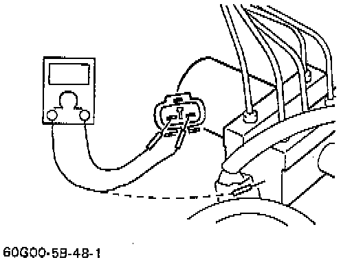
3. Check motor for resistance. Between motor terminals should be less than 1 ohm at 20°C (68°F), and between terminal and motor body should be 1 Megaohm or more.
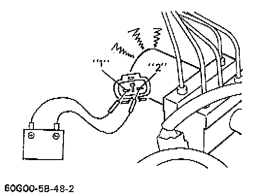
4. Connect 12V battery positive terminal to motor connector terminal "1" and negative terminal to "2". Then check if operation sound is heard from motor. If faulty condition was found in Steps 3 or 4, replace hydraulic unit.