DTC P0400 - Exhaust Gas RECIRCULATION (EGR) Flow Malfunction
- Ensure coolant temperature is less than 104°F (40°C). Start engine. Sharply increase engine speed momentarily and observe EGR valve. Ensure EGR valve does not operate. Allow engine to reach normal operating temperature. Sharply increase engine speed a second time. EGR valve should now operate. If operation is as specified, go to next step. If operation is not as specified, go to step 3).
- With engine at idle, open EGR valve with a glove or shop towel. If engine runs rough or stalls, go to step 10). If engine does not run rough or stall, remove EGR valve and clean intake manifold passage. Retest system.
- Turn ignition off. Check for misrouted, restricted, or leaking vacuum hoses. Repair as necessary. If vacuum hoses are okay, go to next step.
- Disconnect vacuum hose from EGR valve. Connect a hand-held vacuum pump to EGR valve. Apply vacuum and ensure EGR valve opens smoothly and holds vacuum. If operation is as specified, go to next step. If operation is not as specified, replace EGR valve. Retest system.
- Check EGR pressure transducer filter for contamination. Clean if necessary. If filter is okay, go to next step.
- Remove EGR pressure transducer. Plug one vacuum port with finger and blow into remaining vacuum port. Air should pass freely through filter. Connect a hand-held vacuum pump to one vacuum port and plug remaining vacuum port with finger. Blow into pressure port. Apply vacuum to pressure transducer. Vacuum should hold. Stop blowing into pressure port. Vacuum should release. If operation is as specified, go to next step. Replace EGR pressure transducer if operation is not as specified. Retest system.
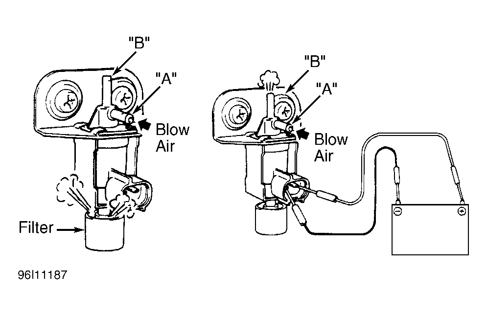
- Reconnect EGR pressure transducer. Disconnect vacuum hoses from EGR solenoid vacuum valve. Turn ignition on. Blow into port "A". See Fig 1
. Air should pass through filter and not from port "B". Using a fused jumper wire, backprobe PCM harness connector "A", terminal No. 6 to ground. Blow into port "A". Air should pass through port "B" and not from filter. If operation is as specified, go to step 10). If operation is not as specified, go to next step.
 Courtesy of SUZUKI OF AMERICA CORP.
- Turn ignition off. Disconnect EGR solenoid vacuum valve harness connector. Using an ohmmeter, measure resistance at solenoid terminals. Resistance should be 33-39 ohms at 68°F (20°C). Resistance between each terminal and body of solenoid should be one megohm or greater. If resistance is as specified, go to next step. If resistance is not as specified, replace EGR solenoid vacuum valve.
- Disconnect vacuum hoses from solenoid. Blow into port "A". See Fig 1
. Air should pass through filter and not from port "B". Using fused jumper wires, connect a 12-volt battery and ground to solenoid terminals. Blow into port "A". Air should pass through port "B" and not from filter. If operation is as specified, check EGR solenoid vacuum valve circuit (White/Blue wire or Green wire) for an open or short. Repair as necessary. If wire(s) are okay, replace PCM. If operation is not as specified, replace EGR solenoid vacuum valve. Retest system.
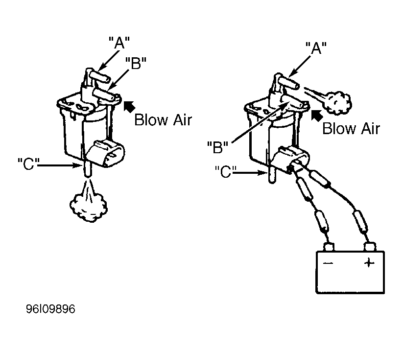
- Turn ignition off. Using a fused jumper wire, connect PCM harness connector "A", terminal No. 5 (Red/Black wire) to ground. Disconnect vacuum hoses from EGR system check solenoid. See Fig 2
. Turn ignition on. Blow into port "B". Air should pass through port "A" and not port "C". Turn ignition off. Disconnect jumper wire. Blow into port "B". Air should pass through port "C" and not port "A". If operation is not as specified, go to next step. If operation is as specified, check for poor connection at PCM. Repair as necessary. If connection is okay, replace PCM. Retest system.
 Courtesy of SUZUKI OF AMERICA CORP.
- Turn ignition off. Disconnect EGR system check solenoid harness connector. Using an ohmmeter, measure resistance between solenoid terminals. Resistance should be 33-39 ohms at 68°F (20°C). Resistance between each terminal and body of solenoid should be one megohm or greater. If resistance is as specified, go to next step. If resistance is not as specified, replace EGR system check solenoid. Retest system.
- Disconnect vacuum hoses from EGR system check solenoid. Blow into port "B". Air should pass through port "C" and not port "A". If operation is as specified, go to next step. If operation is not as specified, replace EGR system check solenoid. Retest system.
- Using fused jumper wires, connect a 12-volt battery and ground to solenoid terminals. Blow into port "B". Air should pass through port "A" and not port "C". If operation is as specified, check EGR system check solenoid circuit (White/Black wire or Red/Blue wire) for an open or short. Repair as necessary. If wires are okay, replace PCM. If operation is not as specified, replace EGR system check solenoid. Retest system.