Idle Speed
NOTE:
DO NOT
adjust idle speed in areas above 8200 ft. elevation.
IDLE SPEED SPECIFICATIONS
| Application |
RPM |
| With A/C Off |
| Auto. Transaxle |
800-900 |
| Man. Transaxle |
700-800 |
| With A/C On |
| Auto. & Man. Transaxles |
850-950 |
IAC DUTY AT SPECIFIED IDLE SPEED
| Application |
Percent |
| SOHC |
25-35 |
NOTE:
Specified values used for this inspection and adjustment vary depending on type of ECM. Type of ECM can be identified by last digit of ECM part number. Last digit will be "0" or a number other than "0".
- Idle speed is controlled by ECM using IAC valve and requires no adjustments under normal conditions. If conditions require idle speed to be adjusted, start engine and warm it to operating temperature. Turn all accessories off.
- Ensure all fuel and emission control system wire connectors and hoses are properly connected. Ensure accelerator cable has free-play, air cleaner and ducts are properly installed and air filter element is in good condition. Ensure ignition timing is correct.
- Locate monitor coupler beside battery. Using a jumper wire, connect terminal "B" to terminal "C". See Figure
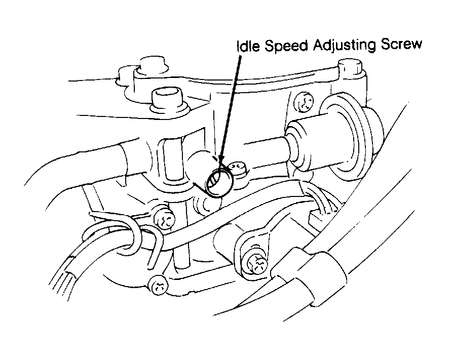
. MIL (CHECK ENGINE light) should indicate Code 12. Attach duty meter terminals "A" and "C". Remove cap and turn idle speed adjusting screw to obtain correct idle speed. See Fig 1
. See the IDLE SPEED SPECIFICATIONS
and the IAC DUTY AT SPECIFIED IDLE SPEED
tables. On vehicles with A/C, verify idle speed is 850-950 RPM with A/C on. If idle speed with A/C on is not within specification check operation of Idle Air Control (IAC) valve. See TESTS W/CODES - 1.3L SOHC
article in the ENGINE PERFORMANCE section.
 Courtesy of SUZUKI OF AMERICA CORP.
- Idle speed is controlled by IAC valve and should not require adjustment. If idle speed needs to be changed, start engine and warm it to operating temperature. Turn all accessories off. Ensure all fuel and emission control system wire connectors and hoses are properly connected. Ensure accelerator cable has free play. Ensure air cleaner and ducts are properly installed and air filter element is in good condition.
- Ensure ignition timing is correct. See IGNITION TIMING
table under IGNITION TIMING. Connect terminal "B" (diagnosis switch) to terminal "D" (ground) using a service wire. See Figure
. MIL (CHECK ENGINE light) should indicate Code 12. Attach duty meter to duty output terminal "F" and ground terminal "D". Remove idle speed adjusting screw protective cap from top of throttle body. See Fig 1
. Turn idle speed adjusting screw to obtain correct idle RPM. See IDLE SPEED SPECIFICATIONS
and IAC DUTY AT SPECIFIED IDLE SPEED
tables.
- On vehicles equipped with A/C, turn A/C switch to ON position and set fan switch to HIGH position. With A/C operating correctly, verify idle is 850-950 RPM and IAC duty is 30-40 percent. If adjustment is required, turn A/C Vacuum Switching Valve (VSV) adjusting screw to obtain correct idle. See IDLE SPEED SPECIFICATIONS
table. Remove service wire, reinstall protective cap to throttle body and recheck idle speed.