Data Link Connector: Description and Operation
Diagnosis And Test Switch Terminals:
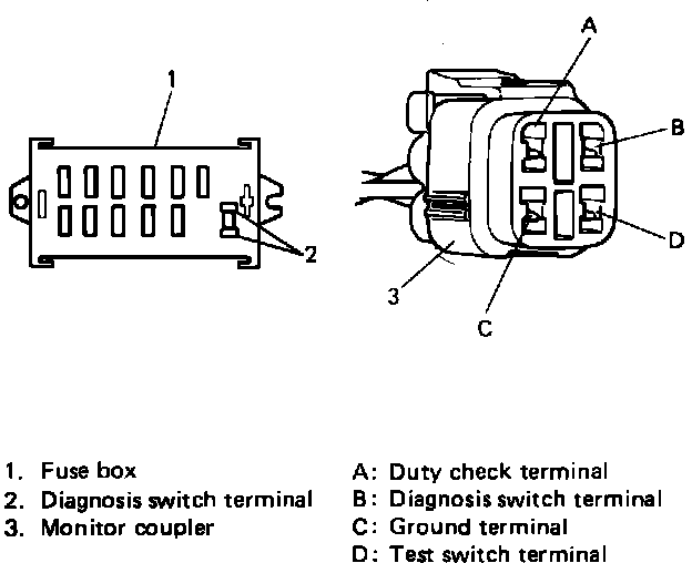
DIAGNOSIS SWITCH TERMINAL
There are two diagnosis switch terminals; one included in the fuse box and the other in the monitor connector in the engine room. When either diagnosis switch terminal is grounded, a diagnosis signal is fed to ECM which then out- puts self-diagnosis code and at the same time outputs ISC duty through duty check terminal.
TEST SWITCH TERMINAL
The test switch terminal is included in the monitor connector. When this terminal is grounded, ECM sets the ignition timing to the specification and turn "CHECK ENGINE" light ON even when engine is running.
When both test switch terminal and diagnosis switch terminal are grounded, ECM outputs A/F duty through the duty check terminal and "CHECK ENGINE" light indicates diagnostic code No. 71, but it is nothing abnormal.