Power Window - Service Information
TSB No.: TS 2-05 05 06190Section Title: Body Electrical
Division: Automotive
Category: Technical
SUBJECT:
POWER WINDOW CONTROL SYSTEM
MODEL: SIDEKICK
YEAR: ALL
The purpose of this bulletin is to provide the following information on the Sidekick power window control system:
1. Location of System Components
2. System Wiring Diagram
3. Operation of System
1. Location of System Components
The power window control system is so designed that it electrically controls up and down movement of side door window glass by means of the motor which is installed to the window regulator.
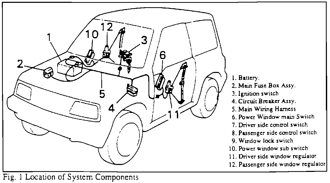
The system consists of the ignition switch, power window switches, window regulator motors and related wiring harness. The figure shows the location of its component parts.
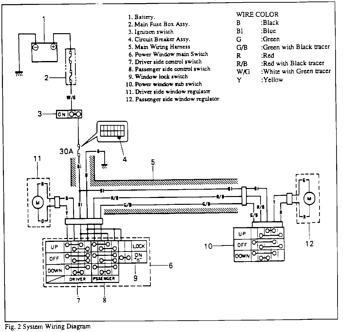
2. System Wiring Diagram
3. Operation of System
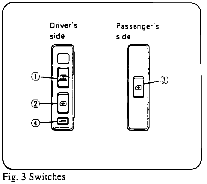
In Fig. 3, the power window main switch in the driver's side door trim controls up and down movement of both driver's side window by switch (1) and passenger's side window by switch (2). The sub switch (3) in the passenger's side door trim controls the passenger's side window only.
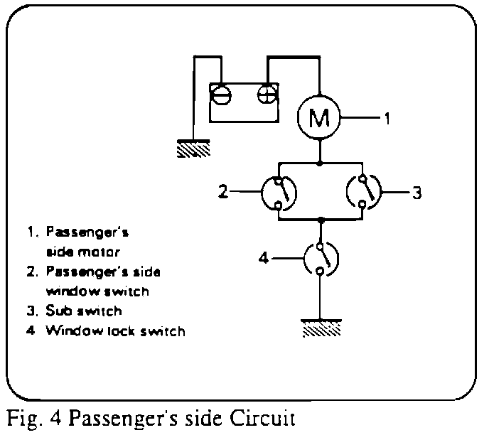
As in Fig. 4, the window lock switch (4) also in the power window main switch locks passenger's side window. As long as this switch is depressed (the switch is turned "OFF" in the circuit), the passenger's side window does not move even when the passenger's side sub switch (3) or driver's side passenger switch C2) are operated. In this system, up and down movement of the window is done as follows.
As power window switch is operated in one direction or the other, an electric current flows to the window regulator motor to run it. Whether the motor turns clockwise or counterclockwise is determined by the direction in which the electric current flows. Thus, the window moves up or down depending on the rotation direction of the motor.
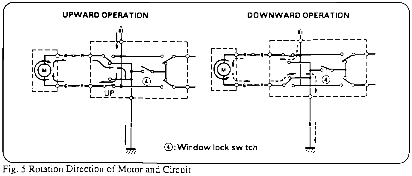
The solid arrow line in Fig. 5 shows the electric current flow when the driver's side switch (1) in Fig. 3) of the power window main switch is operated for upward movement and the broken arrow line for downward movement.
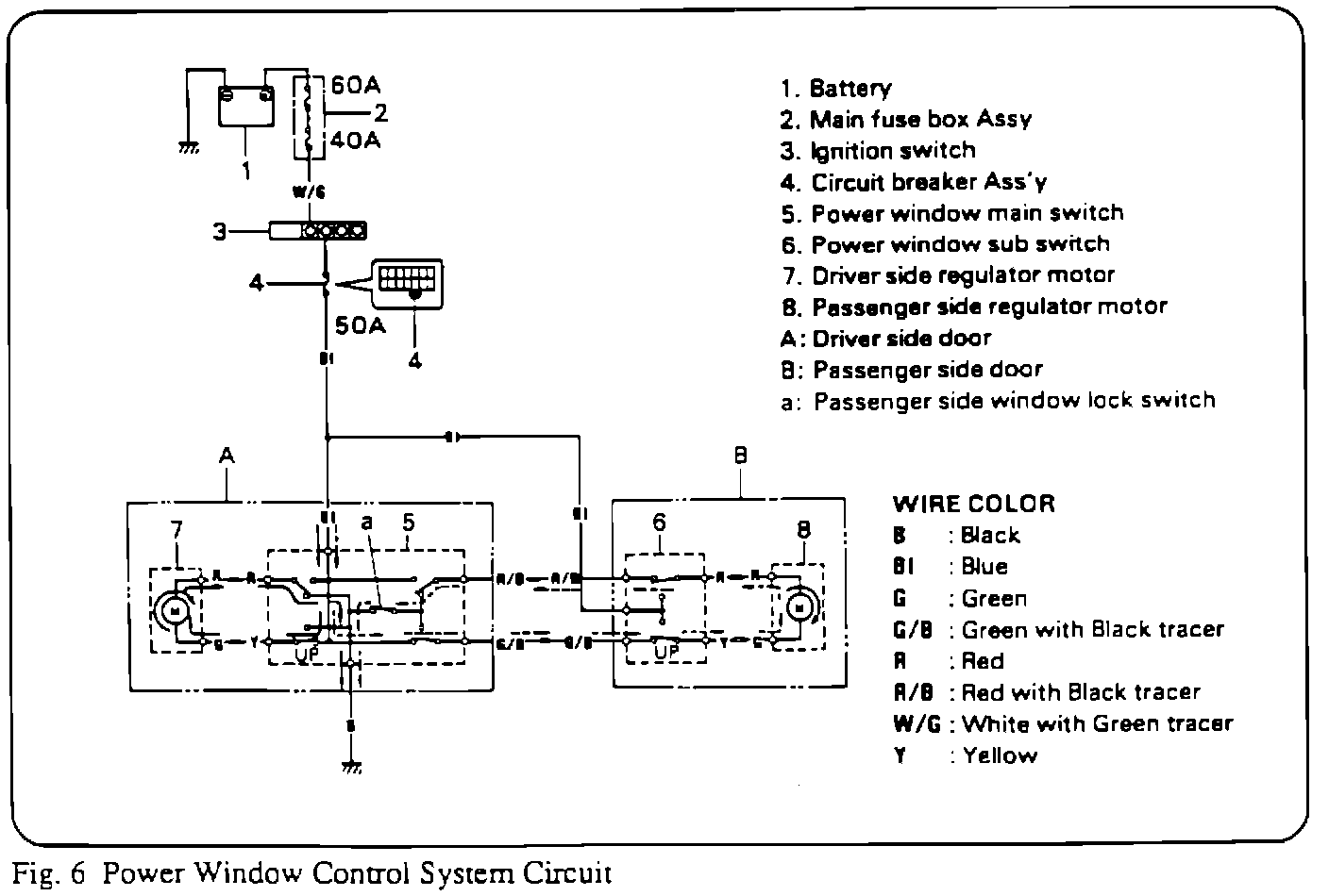
Fig. 6 shows electric current flow when the power window main switch is operated for upward movement of both driver's and passenger's side windows. Electric current flows along the solid arrow line for the driver's side window and along the broken arrow line for the passenger's side window.
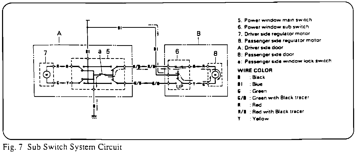
Fig. 7 shows the circuit formed when the sub switch on the passenger's side is operated for upward movement. Electric current flows along the dash and dot line.