Instrument Panel Retainer Replacement
WARNING: This page is about a different car, the 2007 Suzuki XL7. However, it is still accessible from the selected car via links, so may be relevant.
 Courtesy of SUZUKI OF AMERICA CORP.
 INSTRUMENT PANEL RETAINER TABLE
| Callout |
Component Name |
Preliminary Procedures
- Remove the instrument panel upper trim panel. Refer to INSTRUMENT PANEL UPPER TRIM PANEL REPLACEMENT .
- Remove the instrument panel cluster assembly. Refer to INSTRUMENT CLUSTER REPLACEMENT .
- Remove the fasteners securing the steering column to the instrument panel assembly, and lower the column and wheel to the floor of the vehicle out of the way. Refer to REMOVAL PROCEDURE
.
- Remove the instrument panel inflatable restraint. Refer to INFLATABLE RESTRAINT INSTRUMENT PANEL MODULE REPLACEMENT
.
- Remove the radio. Refer to RADIO REPLACEMENT
.
- Remove the global positioning system antenna. Refer to GLOBAL POSITIONING SYSTEM (GPS) ANTENNA REPLACEMENT
.
- Unsnap the ALDL connector from the retainer.
- Remove the instrument panel electrical center. Refer to INSTRUMENT PANEL ELECTRICAL CENTER OR JUNCTION BLOCK REPLACEMENT
.
|
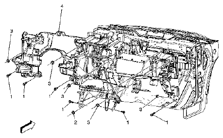
| 1 |
Instrument Panel Retainer Assembly Bolts (Qty 6)
Tightening torque
9 N.m (80 lb in) |
| 2 |
Instrument Panel Retainer Assembly Nut (Qty 1)
Tightening torque
9 N.m (80 lb in)
Tip:
This nut is driven from front of car rearward. All other nuts are driven from rear of car forward. |
| 3 |
Instrument Panel Retainer Assembly Nuts (Qty 5)
Tightening torque
9 N.m (80 lb in) |
| 4 |
Instrument Panel Retainer Assembly
Procedures
- Remove the screws securing the HVAC ducts to the retainer assembly.
- Note the location and routing of the wiring harness and ground straps prior to removal to ensure proper reinstallation.
- Disconnect the wiring harness and ground straps from the retainer assembly.
- With the aid of an assistant, remove the retainer from the vehicle.
|