Timing Belt: Service and Repair
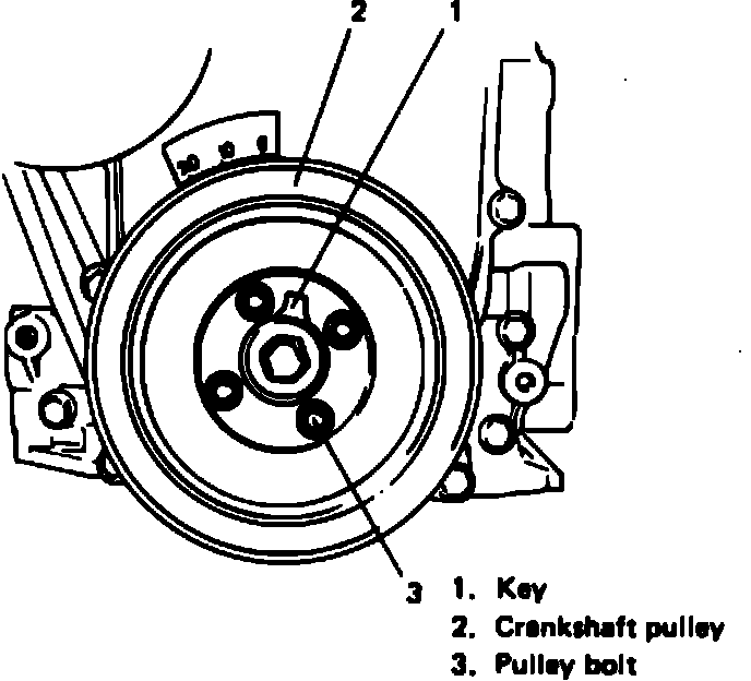
Fig. 1 Crankshaft pulley removal:
1. Disconnect battery ground cable.
2. Loosen fan drive belt and remove bolts securing radiator fan shroud and cooling fan, then remove shroud and fan.
3. Remove water pump belt and pump pulley.
4. Remove crankshaft pulley attaching bolts and the pulley, Fig. 1. It is not necessary to remove crankshaft pulley center bolt.
5. Remove timing belt cover attaching bolts, then timing belt cover.
Fig. 2 Timing belt installation & removal:
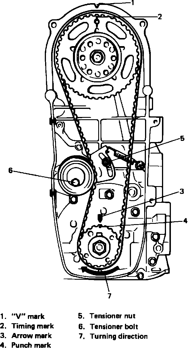
6. Loosen tensioner nut and bolt, Fig. 2, and remove timing belt.
7. Remove valve cover, then loosen all valve adjusting screws all the way to allow free rotation of camshaft.
Fig. 3 Camshaft pulley alignment:
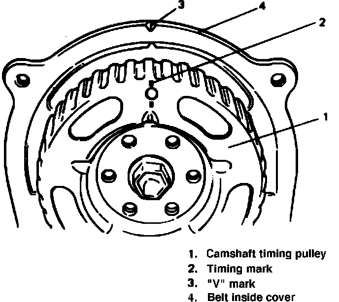
8. Rotate camshaft pulley clockwise and align timing mark on camshaft pulley with ``V'' mark on belt inside cover as shown in Fig. 3.
Fig. 4 Aligning timing belt pulley punch mark with oil pump arrow:
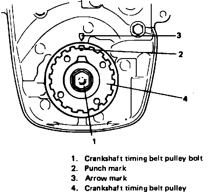
9. Rotate crankshaft clockwise using a 17 mm wrench on crankshaft timing belt pulley bolt, Fig. 4, and align punch mark on timing belt pulley with arrow mark on oil pump as shown in Fig. 4.
Fig. 2 Timing belt installation & removal:
*** UPDATED BY TSB-ST-017-6 AUGUST, 1990.
10. With all timing marks aligned, install timing belt so that drive side of belt is free from any slack with tensioner plate pushed up by finger, Fig. 2. When installing timing belt, match arrow on timing belt with rotating direction of crankshaft.
Note: The belt is uni-directional and the arrows must point toward the rotation of the engine. Damage may occur if improperly installed.
Fig. 5 Adjusting timing belt tension:
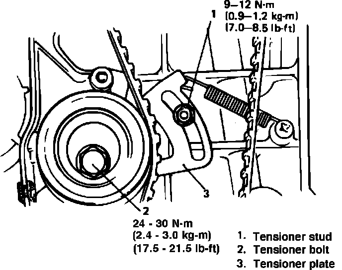
11. Rotate crankshaft two complete revolutions to allow belt to be free of any slack, then tighten tensioner stud to 7-8.5 ft. lbs. and tensioner bolt to 17.5-21.5 ft. lbs., Fig. 5.
12. Install timing belt cover and tighten bolts to 7-8.5 ft. lbs.
13. Install water pump belt and pulley.
Fig. 1 Crankshaft pulley removal:
14. Install crankshaft pulley bolts, Fig. 1, and torque bolts to 7.5-9.0 ft. lbs.
15. Refer to ``Valves, Adjust'' and adjust valve clearance.