Engine Assembly
1. Install selected main bearings into cylinder block, then lubricate bearings with oil. Ensure bearing half with oil hole passage is installed into cylinder block and other half without oil groove to bearing cap. Also ensure that both halves are painted with same color.
2. Install thrust washer to cylinder block between No. 2 and No. 3 cylinders. Ensure to face oil groove sides to crank webs.
3. Install crankshaft into cylinder block, then lubricate journals with oil.
4. Install bearing caps onto journals. Ensure that arrow on each cap is pointing towards crankshaft pulley. Torque cap bolts to 36.5-41.0 ft. lbs., starting from crankshaft pulley side, No. 1. After tightening cap bolts, ensure that crankshaft rotates smoothly when turned by hand.
5. Install oil seal housing and a new gasket. Apply oil to oil seal lip before installing. Torque bolts to 7.5-9.0 ft. lbs.
6. If oil pump was disassembled, assemble as follows:
a. Clean all components using a suitable solvent.
b. Lubricate inner and outer rotors, oil seal lip and inside surfaces of oil pump case and plate with engine oil.
c. Install outer and inner rotors into pump case.
d. Install gear plate. After installing gear plate, ensure that gears rotate smoothly by hand.
7. Install two oil pump pins and a new gasket onto cylinder block.
8. Install Oil Guide Tool 09926-18210, or equivalent, onto crankshaft to prevent oil seal lip damage when installing oil pump assembly.
9. Install oil pump attaching pumps. Torque bolts to 7-8.5 ft. lbs.
10. install piston rings onto piston as follows:
Fig. 13 Piston installation:
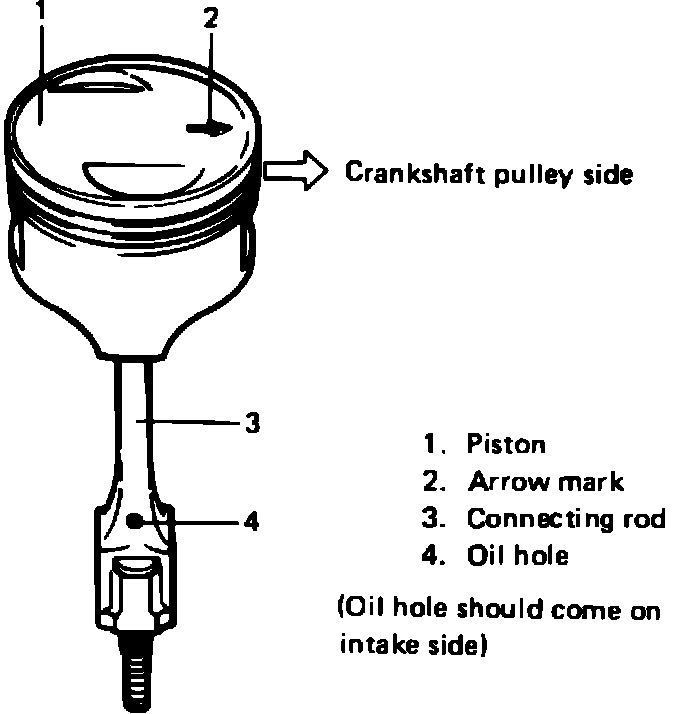
a. Apply engine oil to piston pin bores in piston and rod and fit connect rod to piston as shown in Fig. 13.
Fig. 22 Piston pin installation:
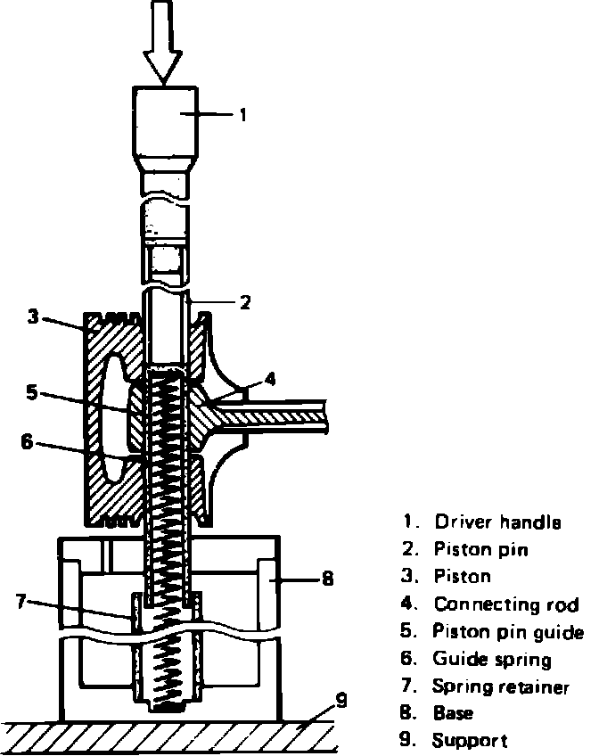
b. Place piston on tool 09910-38210 so arrow mark on piston head faces up. Press piston pin into piston and connecting rod, Fig. 22.
Fig. 23 Piston ring installation:
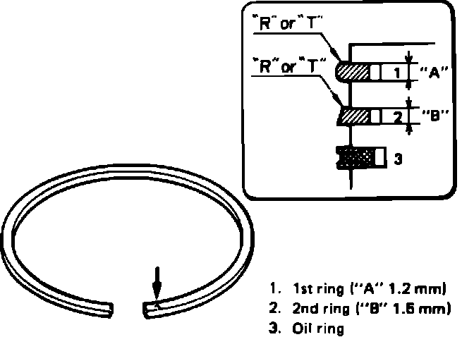
c. Install piston rings so mark side of each ring faces top of piston, Fig. 23. Note shape of of rings 1 and 2.
d. Install oil ring spacer first, then 2 rails.
Fig. 13 Piston installation:
Fig. 24 Ring end gap alignment:
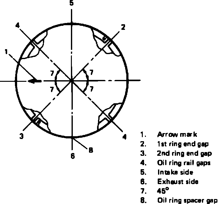
e. Align ring end gaps as shown in Fig. 24. Pistons and connecting rod assemblies must be installed in block so arrows on pistons face front (pulley end) of engine, Fig. 13.
11. Install connecting rod bearing caps. Torque cap nuts to 24-26.5 ft. lbs. Ensure that arrow (marked on each bearing cap) points towards crankshaft pulley side.
Fig. 25 Measuring rod bearing side clearance:
12. Using a suitable feeler gauge, measure side clearance of connecting rod big end, Fig. 25. Big end side clearance should be 0.0039-0.0078 inch (0.10-0.20 mm), and must not exceed 0.0137 inch (0.35 mm). If clearance exceeds limit, replace connecting rod.
13. Install oil pump strainer. Torque bolts to 6.5-8.5 ft. lbs.
14. Apply suitable sealant to oil pan, then install oil pan. Torque bolts, starting at center, to 7-8.5 ft. lbs.
15. Install gasket on drain plug, then drain plug into oil pan. Torque drain plug to 22-28.5 ft. lbs.
16. Install guide seal into oil pump case, then oil dipstick.
17. Install flywheel to crankshaft, then Flywheel Holder 09924-17810. Torque flywheel attaching bolts to 41.5-47 ft. lbs.
18. Install valve guides into cylinder head as follows:
a. Ream guide hole using a 12 mm reamer, to remove any burrs. Ensure guide hole diameter is 0.4736-0.4743 inch (12.030-12.048 mm) after reaming.
b. Heat cylinder head to approximately 176-212° F (80-100° C), then using tools 09917-88210 and 09916-57321, drive in new valve guide until valve guide protrudes 0.55 inch (14 mm) from cylinder head.
c. Using a 7 mm reamer, ream valve guide bore. After reaming, clean bore.
19. Install valve spring seat to cylinder head, then valve stem seal to valve guide.
20. Lubricate stem seal, valve guide bore and valve stem, then install valve into valve guide.
21. Install valve springs, then retainers using a suitable valve spring compressor. Ensure to install springs with bottom end (small pitch end) down to valve spring seat.
Fig. 26 Cylinder head tightening sequence:
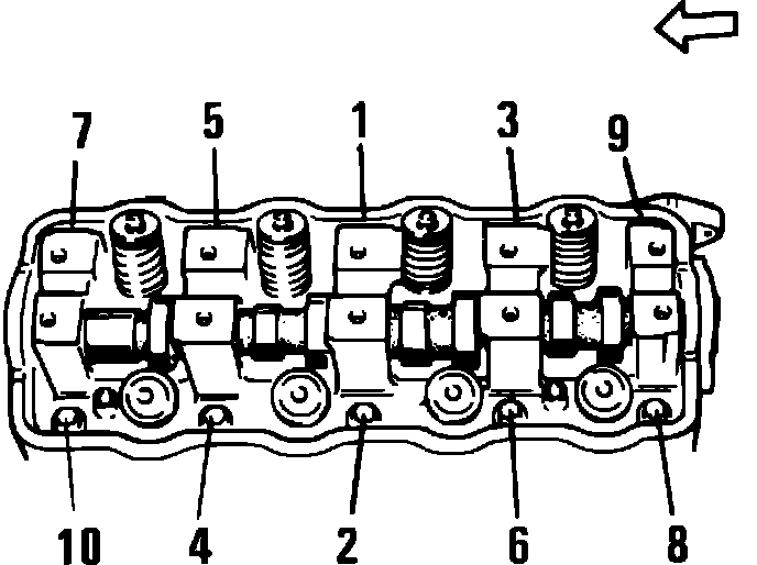
22. Install new head gasket, then cylinder head onto cylinder block. Torque bolts to 46-50.5 ft. lbs. as shown in Fig. 26.
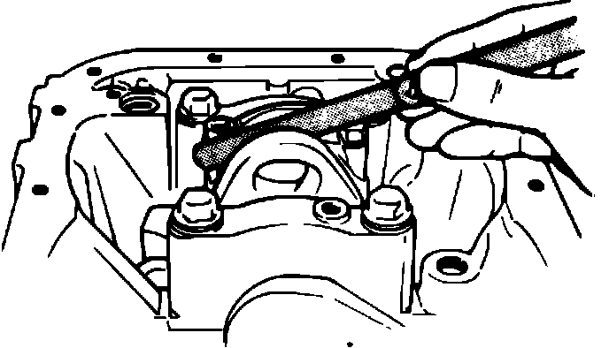
23. Apply engine oil onto camshaft, then install camshaft from transmission case side.
Fig. 27 Intake & exhaust rocker arm shaft identification:
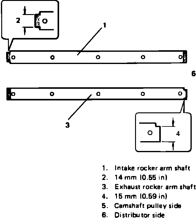
24. Lubricate rocker arms and rocker arm shafts, then install rocker arms, springs and rocker shafts. Rocker arm shafts are not identical. Dimensions of their stepped ends differ as shown in Fig. 27. Install intake rocker arm shaft, facing stepped end to camshaft pulley side and exhaust rocker arm shaft, facing its stepped end to distributor side (rear side).
25. Torque rocker arms shaft screws to 7-8.5 ft. lbs.
26. Install water inlet pipe to cylinder block. Ensure to install new O-ring to inlet pipe before installing.
27. Install intake manifold with carburetor using a new gasket. Torque bolts to 13.5-20 ft. lbs.
28. Connect water hoses to water inlet pipe, and secure hoses with clamps.
29. Install oil filter.
30. Install exhaust manifold using a new gasket, and torque bolts to 13.5-20 ft. lbs.
31. Install water pump and new gasket. Torque bolts to 7-8.5 ft. lbs.
32. Install two rubber seats, one between oil pump and water pump and the other between water pump and cylinder head.
33. Install timing belt inside cover, then crankshaft timing belt guide, key and pulley. Torque timing belt pulley bolt to 47.5-54 ft. lbs.
34. Install camshaft timing belt pulley key, then pulley. Torque pulley bolt to 41-46 ft. lbs.
35. Install timing belt tensioner, tensioner plate and spring.
36. Refer to ``Timing Belt, Replace,'' and install timing belt as outlined.
37. Install crankshaft pulley key, then crankshaft pulley. Torque pulley bolts to 7.5-9 ft. lbs.
38. Install alternator.
39. Install distributor case 0-ring to cylinder block, then distributor case. Torque bolts to 6-8.5 ft. lbs. After tightening distributor case, fill distributor case with approximately 1 ounce of engine oil.
40. Install fuel pump rod, gasket and fuel pump onto cylinder head. Lubricate rod with engine oil before installing.
41. Install clutch disc and cover using Alignment Tool 09923-38220, or equivalent, and torque bolts to 13.5-20 ft. lbs.
42. Install transmission assembly onto engine. Torque bolts to 16-25 ft. lbs.
43. Install distributor assembly into distributor case, then connect spark plug wires.
44. Refer to ``Valves, Adjust,'' and adjust valve clearance as outlined.
45. Install valve cover. Torque bolts to 3-3.5 ft. lbs. and check ignition timing.