September 30: LEMON manuals is back up on a temporary server! Slowness is possible
Removal Procedure
- Remove the knee bolster. Refer to Knee Bolster Replacement
in Instrument Panel, Gages, and Console.
- Remove the closeout panel. Refer to Closeout/Insulator Panel Replacement - Left
in Instrument Panel, Gages, and Console.
- Remove the electrical connector from the brake apply sensor.
- Remove the electrical connector from the brake pedal adjustment position sensor.
- Remove the steering column assembly from the vehicle. Refer to Steering Column Replacement
in Steering Wheel and Column.
- Remove the cable from the adjustable pedal assemblies. Refer to Adjustable Brake Pedal Cable Replacement .
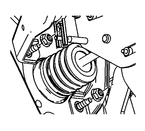 Courtesy of GENERAL MOTORS CORP.
- Remove the 2 brake pedal assembly to cowl mounting nuts.
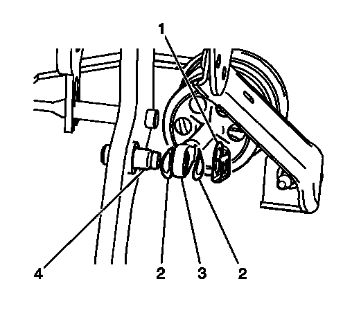 Courtesy of GENERAL MOTORS CORP.
- Remove the booster pushrod retaining clip (1), the washers (2), and the booster pushrod (3) from the adjustable pedal pivot pin (4).
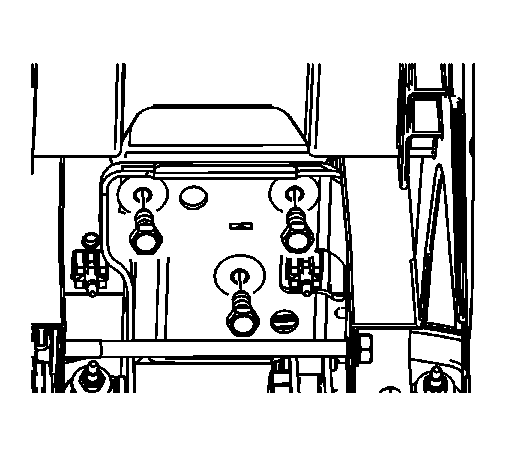 Courtesy of GENERAL MOTORS CORP.
- Remove the 3 brake pedal assembly to instrument panel (I/P) carrier bolts.
- Remove the adjustable brake pedal assembly from the vehicle.