October 30: LEMON manuals on a temporary server, it is slow and having issues, download the manuals you need! Later in November we will switch back to the fast server.
Control System Component Part Configuration Diagram
| Name |
Symbol |
Name |
Symbol |
| CVT assembly (Solenoid valve assembly, transmission fluid temperature sensor) |
D |
Shift lock solenoid |
I |
| Data link connector |
H |
Shift switch assembly |
I |
| Paddle shift switch |
G |
TCM |
F |
| Primary pulley speed sensor |
E |
Transmission range switch |
B |
| Secondary pulley speed sensor |
A |
Turbine speed sensor |
C |
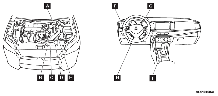 Courtesy of MITSUBISHI MOTOR SALES OF AMERICA.
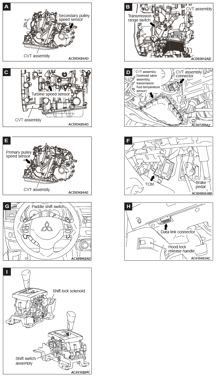 Courtesy of MITSUBISHI MOTOR SALES OF AMERICA.