October 30: LEMON manuals on a temporary server, it is slow and having issues, download the manuals you need! Later in November we will switch back to the fast server.
Entering On-Board Diagnostics (Using Voltmeter)
- Before entering on-board diagnostics, refer to PRETEST INSPECTION
in this article. Turn ignition switch to OFF position. Locate self-diagnostic connector. See SELF-DIAGNOSTIC TEST CONNECTOR LOCATION
table. Using an analog voltmeter, connect voltmeter positive lead to self-diagnostic connector terminal No. 1 and negative lead to terminal No. 12 (ground). See Figure
.
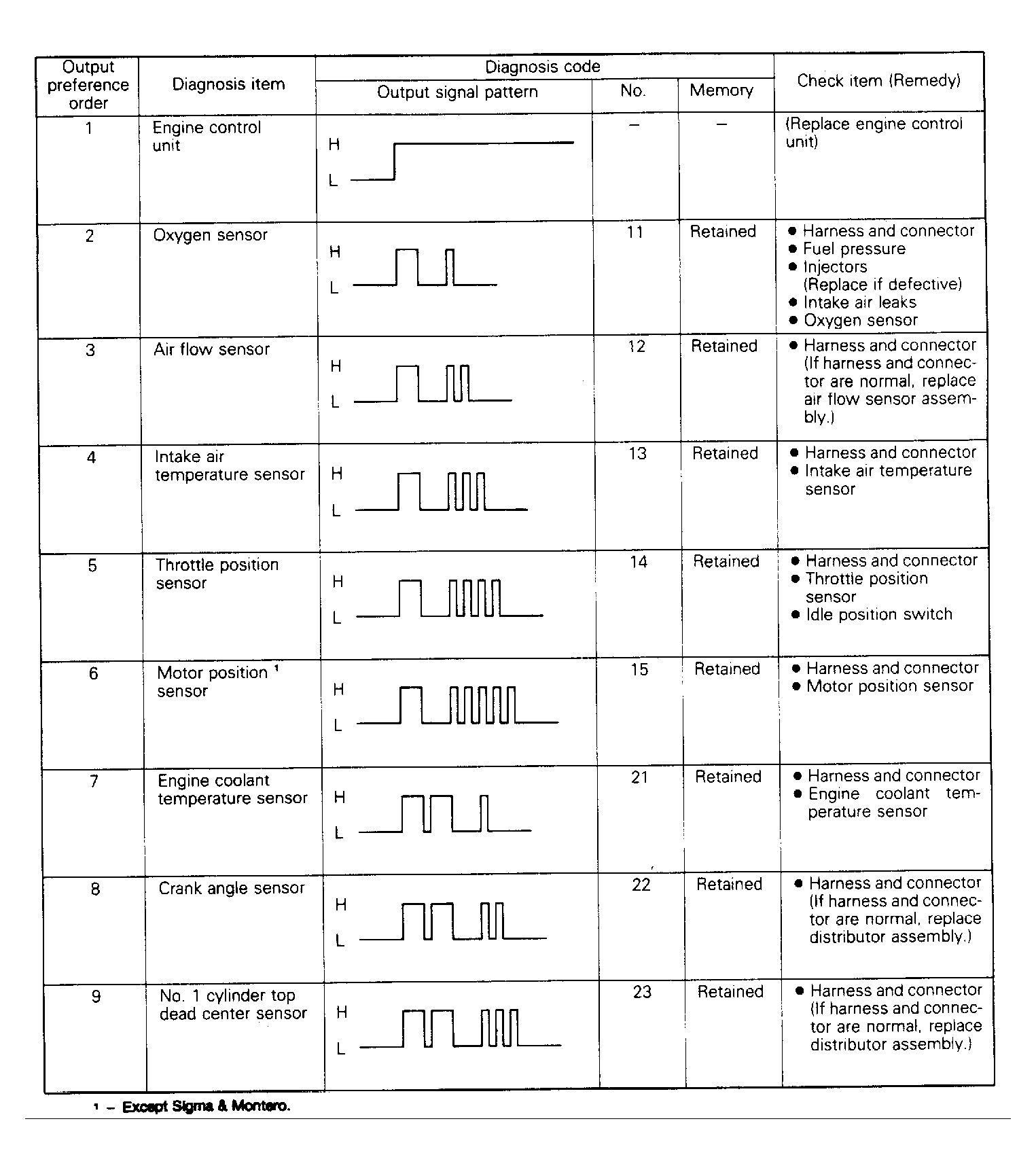
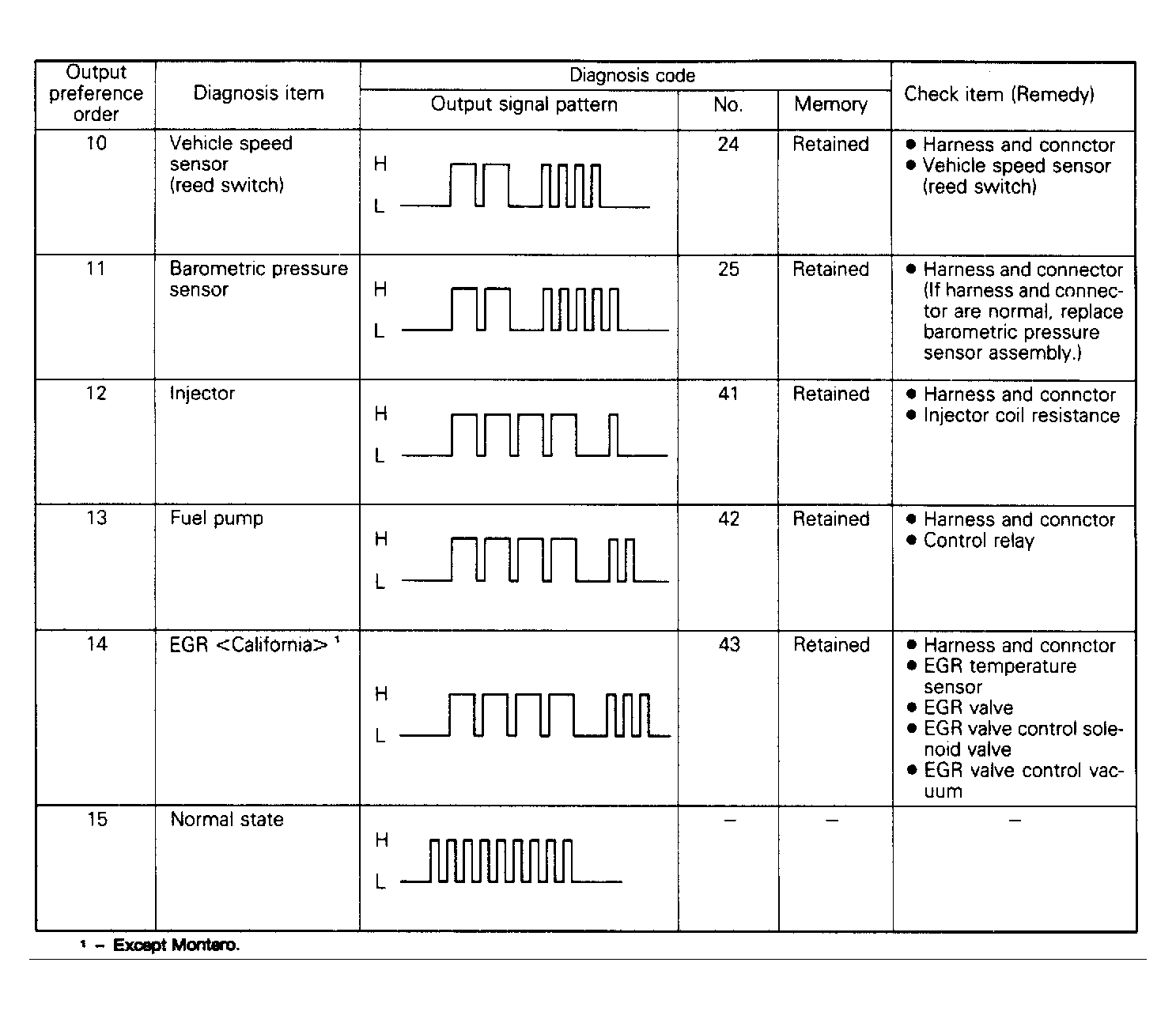
- Turn ignition switch to ON position and disclosure of ECU memory will begin. If 2 or more systems are non-functional, they are indicated by order of increasing code number. Indication is made by 12-volt pulses of voltmeter pointer. A constant repetition of short 12-volt pulses indicates system is normal. If system is abnormal, voltmeter will pulse between zero and 12 volts.
- Signals will appear on voltmeter as long and short 12-volt pulses. Long pulses represent tens; short pulses represent ones. For example 4 long pulses and 3 short pulses indicates Code 43. See Fig 1
and Fig 2
. After recording abnormal code(s), perform necessary repair.
- After repair, turn ignition off and disconnect negative battery cable for 10 seconds to erase ECU memory. Reconnect power supply and repeat self-diagnostics to confirm repair.
SELF-DIAGNOSTIC TEST CONNECTOR LOCATION
| Application |
Location |
| Colt, Colt 200, Colt Wagon & Summit |
| 1.5L |
Next to fuse block |
| 1.6L |
Right kick panel |
| Colt Wagon & Colt Vista 1.8L & 2.0L SOHC |
Next to fuse block |
| Eclipse |
Next to fuse block |
| Galant |
Left kick panel |
| Mirage |
Left kick panel |
| Montero |
Inside top of glove box |
| Precis |
Left kick panel |
 Courtesy of MITSUBISHI MOTOR SALES OF AMERICA.
 Courtesy of MITSUBISHI MOTOR SALES OF AMERICA.