 |
Risk of injury.
Skin or eye injuries may result when handling hot or glowing objects. |
Wear protective gloves, protective clothing and safety glasses, if necessary. |
AS00.00-Z-0002-01A |
| |
Notes on avoiding damage through contamination and foreign objects |
|
AH00.00-P-5000-01A |
  |
Remove/install |
|
|
| 1 |
Clamp off ground line of on-board electrical system battery (G1). |
|
AR54.10-D-0029TS |
| 2 |
Remove left engine carrier. |
|
AR22.10-D-4350TSC |
| 3 |
Release and disconnect electrical connector (21) on alternator (22). |
|
|
| 4 |
Remove cover (19). |
|
|
| 5 |
Unscrew nut and detach electric line (20) from alternator (22). |
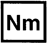 Nut, line to alternator
 |
*BA15.40-N-1002-01X |
| 6 |
Release and disconnect electrical connector of valve (26). |
|
|
| 7 |
Remove screws/bolts (6). |
Bolt, oil separator to crankcase |
*BA01.20-N-1006-01W |
| 8 |
Remove oil separator (3) from crankcase. |
 Replace seal.
 |
|
| 9 |
Open clamp (5) and push on the vent line (4) in the direction of the oil separator (3). |
 Hose clamp pliers
 |
Fig 1 |
| 10 |
Remove vent line (4) from charge-air distributor. |
|
|
| 11 |
Remove purge line (15) on distributor (17). |
|
|
| 12 |
Remove screw/bolt (16). |
Screw/bolt, housing vent to charge air distributor |
*BA09.41-N-1005-01V |
| 13 |
Remove distributor (17) from charge-air distributor. |
Replace sealing ring (18). |
|
| 14 |
Remove engine air intake duct downstream of air filter. |
|
AR09.10-D-8130TSC |
| 15 |
Remove vacuum line (7) from air intake pipe (1). |
|
|
| 16 |
Remove vent line (8) from air intake pipe (1). |
|
|
| 17 |
Remove vent line (9) from air intake pipe (1). |
|
|
| 18 |
Remove clamps (10). |
|
|
| 19 |
Release clamp (11). |
Position screw part of the clamp (11) for marking (12) on the air intake pipe (1). |
|
| 20 |
Remove air intake pipe (1). |
|
|
| 21 |
Remove sealing ring between air intake pipe (1) and exhaust gas turbocharger. |
 The sealing ring must first be inserted in the air intake pipe (1) so that crushing of the sealing ring during installation is avoided. Parts of the crushed sealing ring can otherwise be sucked in and severely damage the exhaust gas turbocharger.
The sealing ring must be replaced after every removal. The inside diameter of the sealing ring as well as the fitting of the exhaust gas turbocharger must be wet well with lubricant before assembly. |
|
| |
|
Lubricant |
*BR00.45-Z-1032-06A |
| 22 |
Remove wide open throttle crankcase ventilation system (2) from the brackets (13). |
|
|
| 23 |
Remove screw/bolt (14). |
M6 |
*BA00.10-N-1002-01A |
| 24 |
Remove wide open throttle crankcase ventilation system (2) together with the air intake pipe (1) and the oil separator (3) upwards. |
 The air intake pipe (1) can only be removed together with wide open throttle crankcase ventilation system (2) and the oil separator (3).
Ensure correct installation position. |
|
| 25 |
Install in the reverse order |
|
|
 |
Check |
|
|
| 26 |
Check engine oil level; correct if necessary. |
|
|
 |
Specified engine oils (service) - Overview |
|
BB00.40-P-0223-02A |
 |
|
Engine 274.9 in model 907 except code C6L (Multifunction steering wheel) |
AP18.00-D-1812TSF |
|
|
Engine 274.9 in model 907
with code C6L (Multifunction steering wheel) |
AP18.00-D-1812TSE |
|
Risk of burn injuries,
suffocation and poisoning when working on the exhaust system and the components connected to it. Risk of suffocation and risk of poisoning caused by inhalation of gaseous and solid components of the exhaust. Risk of poisoning
caused by skin contact with solid components of the exhaust. |
Wear protective clothing and safety glasses. Use the extraction system. Move people out of the hazard area. |
AS49.00-Z-0001-01A |
|
Risk of accident
from vehicle starting off by itself when engine running. Risk of injury
(bruises and burns) resulting from working on the engine while it is being started or when it is running. |
Secure vehicle to prevent it from starting off by itself. Wear closed and snug-fitting work clothes. Do not touch hot or rotating parts. |
AS00.00-Z-0005-01A |
| 27 |
Perform engine test run. While doing so, check engine for proper operation and leak tightness. |
|
|