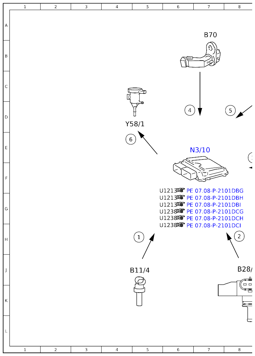
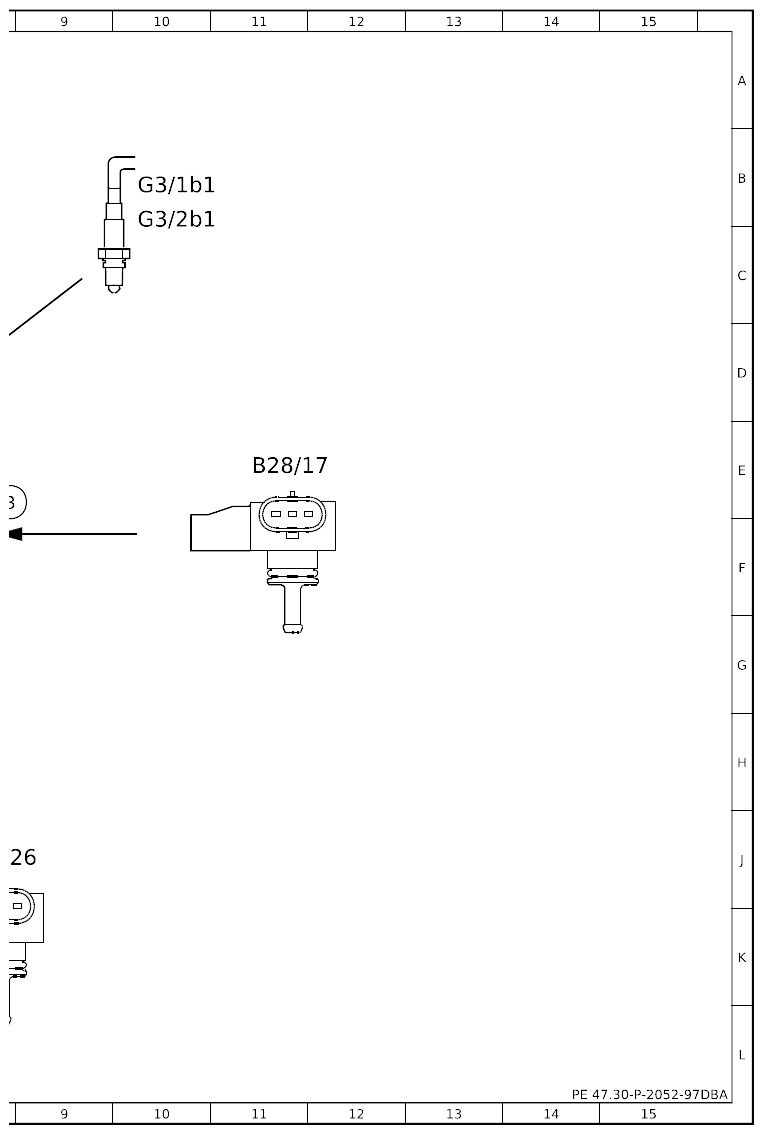
Electrical Function Diagram For Purging Function - PE47.30-P-2052-97DBA
Engine 256.9 in model 213, 238 up to model year 2021
| Code: |
Designation: |
Position: |
| 1 |
Coolant temperature sensor, signal |
5H |
| 2 |
Pressure and temperature sensor upstream of throttle valve, signal |
8H |
| 3 |
Pressure and temperature sensor downstream of exhaust gas turbocharger, signal |
8E |
| 4 |
Crankshaft Hall sensor, signal |
6D |
| 5 |
Oxygen sensor, sensor element, signal |
8D |
| 6 |
Purging switchover valve, actuation |
4E |
| B11/4 |
Coolant temperature sensor |
5J |
| B28/17 |
Pressure and temperature sensor downstream of exhaust gas turbocharger |
11E |
| B28/26 |
Pressure and temperature sensor upstream of throttle valve |
8J |
| B70 |
Crankshaft Hall sensor |
7A |
| G3/1b1 |
Sensor element of oxygen sensor downstream of catalytic converter |
10B |
| G3/2b1 |
Sensor element of oxygen sensor upstream of catalytic converter |
10C |
| N3/10 |
ME-SFI [ME] control unit |
7E |
| Y58/1 |
Purge control valve |
4D |
 Courtesy of MERCEDES-BENZ USA Courtesy of MERCEDES-BENZ USA
|
 Courtesy of MERCEDES-BENZ USA Courtesy of MERCEDES-BENZ USA
|