California Models
Fig. 56 CIS-E I/O Diagram:
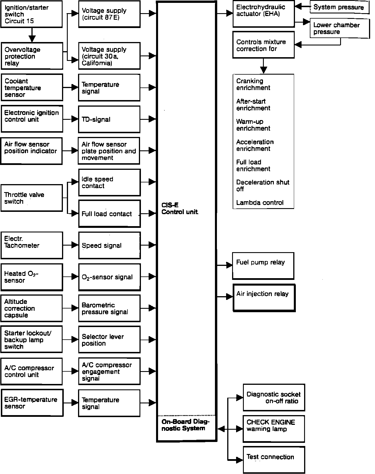
The CIS-E control unit evaluates information provided by various sensors concerning the engine operating conditions.
Fig. 9 CIS-E Control Unit:
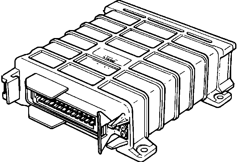
From this information it generates a control signal for the electro-hydraulic actuator. The electro-hydraulic actuator regulates pressure in the lower chambers of the CIS-E fuel distributor which provides for the optimal fuel quantity required by the engine. Furthermore, the CIS-E control unit provides an output signal for operation of the fuel pump relay, air injection relay, diagnostic socket (air/fuel mixture information), "CHECK ENGINE" light operation, and the on-board diagnostic system.
The control unit also incorporates a malfunction memory. All exhaust emission relevant components of the CIS-E injection system and of the EGR system are monitored by the CIS-E control unit.
Fig. 61 Diagnostic Connector:
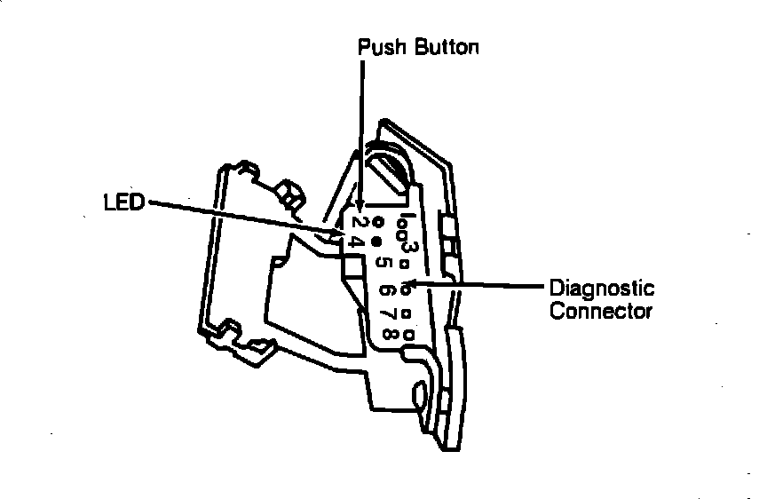
Malfunctions resulting from open or short circuits or failure of one of these components is stored in control unit memory and is indicated by the "CHECK ENGINE" light at the instrument cluster. Recall of the fault memory is accomplished by use of the on-board diagnostic test connector.
See DIAGNOSIS AND TESTING PROCEDURES.