September 30: LEMON manuals is back up on a temporary server! Slowness is possible
Transaxle Support Insulator - 3.5L GTDI: Installation
- Clean the transaxle support insulator bolts using a wire brush and apply new threadlock to the threads.
- Install the 2 upper transaxle support insulator bolts.
- Tighten to 55 Nm (41 lb-ft).
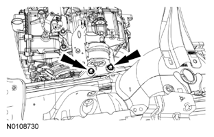 Courtesy of FORD MOTOR CO.
- Install the 2 lower transaxle support insulator bolts.
- Tighten to 55 Nm (41 lb-ft).
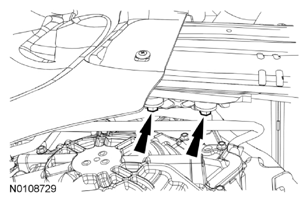 Courtesy of FORD MOTOR CO.
- Install the transaxle support insulator bracket and install the transaxle support insulator bracket bolt and the 3 transaxle support insulator bracket nuts.
- Tighten the transaxle support insulator bracket bolt to 80 Nm (59 lb-ft).
- Tighten the transaxle support insulator bracket nuts to 63 Nm (46 lb-ft).
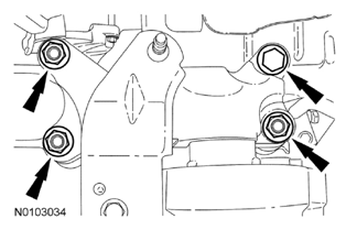 Courtesy of FORD MOTOR CO.
- Remove the Engine Support Bar.
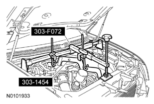 Courtesy of FORD MOTOR CO.
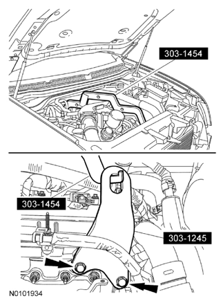
- Remove the 2 front Engine Lift Eye bolts and remove the Engine Spreader Bar and the front Engine Lift Eye.
 Courtesy of FORD MOTOR CO.
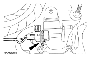
- Connect the turbocharger wastegate regulating valve electrical connector.
 Courtesy of FORD MOTOR CO.
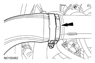
- Position the RH CAC tube, aligning the index marks made during removal and tighten the clamp.
- Tighten to 5 Nm (44 lb-in).
 Courtesy of FORD MOTOR CO.
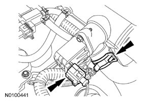
- Connect the LH turbocharger bypass valve electrical connector and the turbocharger bypass valve hose.
 Courtesy of FORD MOTOR CO.
- Install the RH turbocharger-to-CAC hose nut.
- Tighten to 10 Nm (89 lb-in).
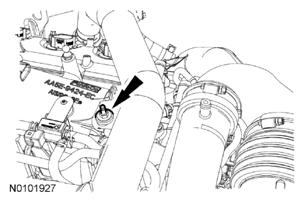 Courtesy of FORD MOTOR CO.
- Position the LH exhaust manifold heat shield in place and install the 4 bolts.
- Tighten to 15 Nm (133 lb-in).
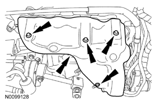 Courtesy of FORD MOTOR CO.
- Install the oil supply tube bracket on the LH valve cover stud bolt and install the nut.
- Tighten to 8 Nm (71 lb-in).
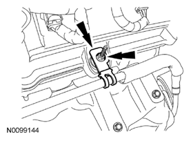 Courtesy of FORD MOTOR CO.
- Attach the wiring harness retainer to the valve cover stud bolt.
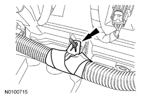 Courtesy of FORD MOTOR CO.
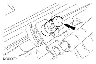
- Install the engine cover mounting stud to the LH valve cover stud bolt.
- Tighten to 6 Nm (53 lb-in).
 Courtesy of FORD MOTOR CO.
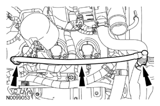
- Install the crankcase vent tube and connect the 2 quick connect couplings.
 Courtesy of FORD MOTOR CO.
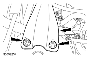
- Install the strut tower brace and the 4 nuts.
- Tighten to 30 Nm (22 lb-ft).
 Courtesy of FORD MOTOR CO.
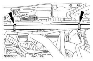
- Attach the vacuum hose clips onto the strut tower brace.
 Courtesy of FORD MOTOR CO.
- Install the cowl panel grille. For additional information, refer to
FRONT END BODY PANELS
.
- Install the battery tray. For additional information, refer to
BATTERY, MOUNTING AND CABLES
.