September 30: LEMON manuals is back up on a temporary server! Slowness is possible
Actuator Power Supply Circuit
- Remove tilt and telescopic control module with connectors connected. With ignition off, measure voltage between connector (T9), terminals No. 4 (Blue/White wire) and No. 7 (White/Black wire). See Fig 1. If voltage is not 10-14 volts, go to next step. If voltage is 1 0-14 volts, go to TROUBLE SHOOTING and identify next circuit to be checked.
- Measure resistance between connector (T9), terminal No. 7 and ground. If resistance is less than one ohm, go to next step. If resistance is one ohm or more, repair open White/Black wire between control module connector (T9), terminal No. 7 and ground, located on left bracket of center console. See WIRING DIAGRAMS.
- Check continuity of PWR (30-amp) fusible link. If continuity does not exist, check and repair short on Blue/White wire between control module connector (T9), terminal No. 4 and fuse block. If continuity does not exist, check for open between control module connector (T9), terminal No. 4 and fuse block.
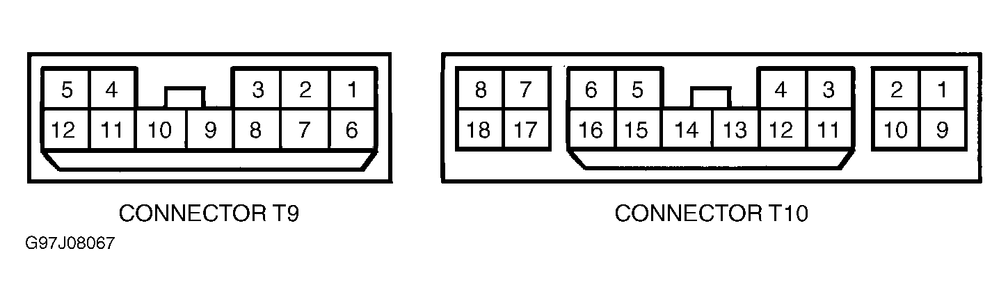 Courtesy of © TOYOTA, LICENSE AGREEMENT TMS1002