Relay Box (Passenger Compartment)
INSPECTION
PASSENGER COMPARTMENT RELAY
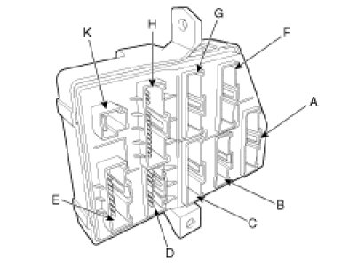
POWER WINDOW
Check for continuity between the terminals.
1. There should be continuity between the No.1 terminal in the I/P-K and the No.9 or 10 terminal in the I/P-G when power and ground are connected to the No.1 terminal in the I/P-K and the No.7 terminal in the I/P-D.
2. There should be no continuity between the No.1 terminal in the I/P-K and the No.9 or 10 terminal in the I/P-G when power and ground are connected to the No.1 terminal in the I/P-K and the No.7 terminal in the I/P-D.
TAIL GATE
Check for continuity between the terminals.
1. There should be continuity between the No.13 terminal in the I/P-H and the No.1 terminal in the I/P-F when power and ground are connected to the No.13 terminal in the I/P-H and the No.17 terminal in the I/P-D.
2. There should be no continuity between the No.13 terminal in the I/P-H and the No.1 terminal in the I/P-F when power and ground are connected to the No.13 terminal in the I/P-H and the No.17 terminal in the I/P-D.
DOOR LOCK
Check for continuity between the terminals.
1. There should be continuity between the No.13 terminal in the I/P-H and the No.7 terminal in the I/P-G or No.12 terminal in the I/P-D when power and ground are connected to the No.13 terminal in the I/P-H and the No.15 terminal in the I/P-D.
2. There should be no continuity between the No.13 terminal in the I/P-H and the No.7 terminal in the I/P-G or No.12 terminal in the I/P-D when power and ground are connected to the No.13 terminal in the I/P-H and the No.15 terminal in the I/P-D.
DOOR UNLOCK
Check for continuity between the terminals.
1. There should be continuity between the No.2 terminal in the I/P-G and the No.2 or 13 terminal in the I/P-E when power and ground are connected to the No.9 terminal in the I/P-D and the No.13 terminal in the I/P-E.
2. There should be no continuity between the No.2 terminal in the I/P-G and the No.2 or 13 terminal in the I/P-E when power and ground are connected to the No.9 terminal in the I/P-D and the No.13 terminal in the I/P-E.
FOG LAMP
Check for continuity between the terminals.
1. There should be continuity between the No.13 terminal in the I/P-H and the No.9 terminal in the I/P-G or the No.1 or No.9 in the I/P-H when power and ground are connected to the No.13 terminal in the I/P-H and the No.16 terminal in the I/P-E.
2. There should be no continuity between the No.13 terminal in the I/P-H and the No.9 terminal in the I/P-G or the No.1 or No.9 in the I/P-H when power and ground are connected to the No.13 terminal in the I/P-H and the No.16 terminal in the I/P-E.
REAR HEATER
Check for continuity between the terminals.
1. There should be continuity between the No.16 terminal in the I/P-H and the No.12 terminal in the I/P-G or the No.16 in the I/P-F and the No.11 in the I/P-E when power and ground are connected to the No.18 terminal in the I/P-C and the No.16 terminal in the I/P-H.
2. There should be no continuity between the No.16 terminal in the I/P-H and the No.12 terminal in the I/P-G or the No.16 in the I/P-F and the No.11 in the I/P-E when power and ground are connected to the No.18 terminal in the I/P-C and the No.16 terminal in the I/P-H.