DTC P0100: Mass Airflow (MAF) Sensor: Procedure
- If malfunction "A" or "C" was duplicated, go to next step. If malfunction "B" or "D" was duplicated, inspect air intake duct and vacuum hoses for disconnection or leaks. Reconnect or repair as necessary. Go to next step.
- Turn ignition off. Loosen and retighten engine ground bolts. See Fig 1. Disconnect MAF sensor harness connector. See Fig 2. Turn ignition on. Measure voltage between MAF sensor harness connector terminal No. 3 (Black/White wire) and ground. If battery voltage exists, go to next step. If battery voltage does not exist, repair open or short circuit. See appropriate wiring diagram in WIRING DIAGRAMS article.
- Turn ignition off. Disconnect ECM harness connector. See Figure. Check continuity of Black wire between MAF sensor harness connector terminal No. 2 and ECM harness connector terminal No. 55. See Figure. If continuity exists, go to next step. If continuity does not exist, repair open in Black wire.
- Check continuity of White wire between MAF sensor harness connector terminal No. 1 and ECM harness connector terminal No. 54. If continuity exists, go to next step. If continuity does not exist, repair open in White wire.
- Reconnect all harness connectors. Start engine and warm to normal operating temperature. Measure voltage between ground and ECM harness connector terminal No. 54 by backprobing. See Figure. See MASS AIRFLOW SENSOR VOLTAGE table.
- If voltage is as specified, go to next step. If voltage is not as specified, disconnect and reconnect MAF sensor harness connector. Repeat step 5. If voltage is still not as specified, check for dust or foreign material in hot wire air passage of MAF sensor. If air passage is okay, replace MAF sensor and retest system.
- Check shield circuit for continuity to ground. Shield is connected to ground through connector F-21 (Blue, 12-pin joint connector located near ECM). See appropriate wiring diagram in WIRING DIAGRAMS article. If continuity does not exist, repair open circuit. If continuity exists, no problem is currently indicated. Problem may be intermittent. See TESTING PROCEDURE under SELF-DIAGNOSTIC SYSTEM in SELF-DIAGNOSTICS - INTRODUCTION article.
MASS AIRFLOW SENSOR VOLTAGE
| Condition |
Volts |
| Key On, Engine Off |
Less Than 1.0 |
| Engine Idling |
1.0-1.7 |
| 2500 RPM |
1.7-2.3 |
| Idle To 4000 RPM |
1.0-1.7 To About 4.0 |
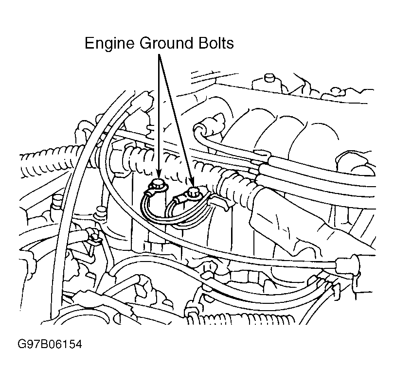 Courtesy of NISSAN MOTOR CO., U.S.A.
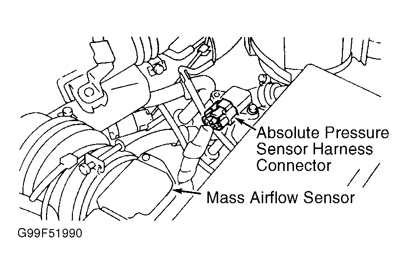 Courtesy of NISSAN MOTOR CO., U.S.A.