September 30: LEMON manuals is back up on a temporary server! Slowness is possible
Steering Column Removal and Installation: Removal
- Do the 12 volt battery terminal disconnection procedure (see
12 VOLT BATTERY TERMINAL DISCONNECTION AND RECONNECTION
).
- Release the lock lever, and adjust the steering column to the full tilt up position, and to the full telescopic in position.
- Tighten the lock lever.
- Remove the driver's airbag (see
DRIVER'S AIRBAG REPLACEMENT
) and the steering wheel (see STEERING WHEEL REMOVAL
).
- Remove the driver's dashboard undercover (see
DRIVER'S DASHBOARD UNDERCOVER REMOVAL/INSTALLATION
).
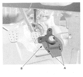
- Release the hooks (A), then remove the steering joint cover (B).
 Courtesy of AMERICAN HONDA MOTOR CO., INC.
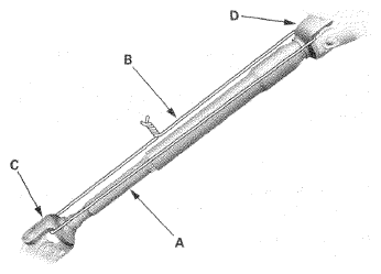
- Hold the splined shaft (A) on the column with a piece of wire (B) between the joint yoke (C) of the splined shaft and joint yoke (D) of the splined tube to prevent the splined shaft from pulling out.
 Courtesy of AMERICAN HONDA MOTOR CO., INC.
- Release the lock lever, and adjust the steering column to the full telescopic out position, then tighten the lock lever.
NOTE:
Do not release the lock lever when removing the steering column from the frame.
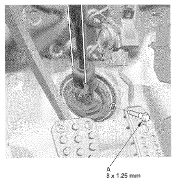
- Remove the steering joint bolt (A).
 Courtesy of AMERICAN HONDA MOTOR CO., INC.
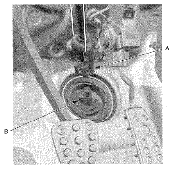
- Disconnect the steering joint (A) by moving the steering joint toward the column.
NOTE:
- If the center guide (B) is in place and has not moved, leave it in place.
- If the center guide has moved or been removed, discard it.
 Courtesy of AMERICAN HONDA MOTOR CO., INC.
- Remove the column covers (see
COLUMN COVER REMOVAL/INSTALLATION
).
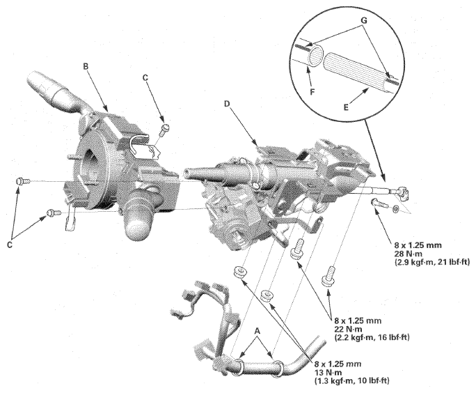
- Disconnect the connectors from the ignition switch, and release the wire harness clips (A) from the steering column.
 Courtesy of AMERICAN HONDA MOTOR CO., INC.
- Disconnect the connectors from the combination switch assembly/cable reel (B).
- Remove the combination switch assembly/cable reel from the steering column shaft by removing the three screws (C).
- Remove the steering column (D) by removing the attaching nuts and bolts. If the splined shaft (E) is removed, slip it into the splined tube (F) by aligning the paint or stamped marks (G).
NOTE:
Do not release the lock lever until the steering column is installed. If the lock lever is released before installation, adjust the steering column after installation.